Simulated Source Settings
Use the Configure Source Type dialog to configure the fundamental settings of your simulated source waveform. Once your waveform is defined, click Output Enable button to turn on the waveform. The button is green when the waveform is enabled. To view the waveform on the oscilloscope, click the channel button in the Configure Simulation Source dialog. Select Invert Signal to invert the waveform.
Always perform an Auto Scale after configuring the source waveform.
Source Waveform Type
Pattern Selections for Simulated NRZ Waveforms
- One - Zero
- PRBS-7 (127 symbols)
- PRBS-7 (128 symbols)
- PRBS-9 (511 symbols)
- PRBS-9 (512 symbols)
- PRBS-11 (2047 symbols)
- PRBS-11 (2048 symbols)
- PRBS-13 (8191 symbols)
- PRBS-13 (8192 symbols)
- PRBS-15 (32767 symbols)
- PRBS-15 (32768 symbols)
- JP01A (2 symbols)
- JP01B (62 symbols)
- JP01C (6 symbols)
- K28.5 (20 symbols)
- SSPR (32762 symbols)
Pattern Selections for Simulated PAM Waveforms
- PRBS-7 (127 symbols)
- PRBS-7 (128 symbols)
- PRBS-9 (511 symbols)
- PRBS-9 (512 symbols)
- PRBS-11 (2047 symbols)
- PRBS-11 (2048 symbols)
- PRBS-13 (8191 symbols)
- PRBS-13 (8192 symbols)
- PRBS-15 (32767 symbols)
- PRBS-15 (32768 symbols)
- Linearity (160 symbols)
- JP03A (2 symbols)
- JP03B (62 symbols)
- JP03C (62 symbols)
- SSPRQ (65535 symbols)
Use the Waveform Type field to select a Data, Clock, Function, or Load from File. The Format can be selected from NRZ, PAM4, PAM6, and PAM8. For Function waveforms, you can select from the functions: Sine, Cosine, Square, Triangle, and Sawtooth.
For Data waveforms, use the Format field to select the type of simulated data format: NRZ or PAM4. Select the Pattern from one that is shown in these side bars.
If you select Load from File, you can click Browse to select a pattern waveform file. Both .wfmx and .csv formats are supported. This feature allows you to work offline with your data. It is recommended that you also save a FlexDCA setup file when you save your original waveform. When you load the waveform file, also load the setup file to ensure that the FlexDCA settings match those of your waveform file
Waveform Symbol Rate
Symbol Rate Selections for Simulated Waveforms
- 51.84 MBd - STM-0/OC-1
- 125.0 MBd - FDDI/100M Ethernet
- 155.52 MBd - STM-1/OC-3
- 270.0 MBd - SDI
- 614.4 MBd - CPRI
- 622.08 MBd - STM-4/OC-12
- 768.00 MBd - OBSAI
- 1.06250 GBd - 1G Fibre Channel
- 1.22880 GBd - CPRI 2x
- 1.244160 GBd - GPON/OC-24
- 1.25000 GBd - Gb Ethernet
- 1.48500 GBd - SDI
- 1.50000 GBd - SATA-1/SAS-1
- 1.53600 GBd - OBSAI 2x
- 2.12500 GBd - 2B Fibre Channel
- 2.4576 GBd - CPRI 4x
- 2.48832 GBd - STM-16/OC-48
- 2.50000 GBd - PCIe1/2 Gb Ethernet/InfiniBand
- 2.6660570 GBd - STM-16/OC-48 FEC
- 2.97000 GBd - SDI
- 3.00000 GBd - SATA-2/SAS-2
- 3.07200 GBd - CPRI 5x / OBSAI 4x
- 3.12500 GBd - XAUI / 10GbE Base-LX4
- 3.18750 GBd - FC-3187/10GBE Base-LX4
- 3.25000 GBd - Rapid IO
- 3.32000 GBd - 12x Parallel Optics
- 4.25000 GBd - 4G Fibre Channel
- 4.9152 GBd - CPRI 8x
- 5.00000GBd - PCIe-2/2x InfiniBand
- 6.00000 GBd - SATA-3/SAS3/CEI
- 6.144 GBd - CPRI 10X / OBSAI 8X
- 6.25000 GBd - 2x XAUI
- 6.37500 GBd - CEI 6G+
- 8.00000 GBd - PCIe-3
- 8.1100800 GBd - CPRI 16x
- 8.50000 GBd - 8x Fibre Channel
- 9.8304 GBd - CPRI 16x
- 9.95328 GBd - STM-64/OC-192/10GbEthernet
- 10.00 GBd - InfiniBand QDR
- 10.1376 GBd - CPRI 20x
- 10.3125 GBd - 10Gb Ethernet LR/ER
- 10.51875 GBd - 10G Fibre Chanel
- 10.664230 GBd - STM-64/OC-192 FEC
- 10.7090 GBd - STM-64/OC-192 FEC
- 11.0000 GBd - CEI 11G
- 11.0957 GBd - 10Gb Ethernet FEC
- 11.3170 GBd - 10GFC FEC
- 12.165120 GBd - CPRI 24x
- 12.249450 GBd - STM-64/OC-192 SuperFEC
- 12.44160000 GBd - ITU-T PON
- 14.025000 GBd - 16G Fibre Channel
- 14.06250 GBd - InfiniBand FDR
- 16.00000 GBd - PCIe-4
- 24.33024000 GBd - CPRI 48x
- 24.88320000 GBd - ITU-T PON
- 25.78125 GBd - 100GbE/4 / InfiniBand EDR
- 26.56250000 GBd - 400GBASE-SR16
- 27.7393 GBd - 100Gb Ethernet / 4 FEC
- 27.952493 GBd - OTU4/ITU-T G.959.1
- 28.05 GBd - 32G Fibre Channel
- 28.9 GBd - 64G Fibre Channel
- 32.00000 GBd - PCIe-5/PCIe-6
- 39.81312 GBd - STM-256/OC-768
- 41.250000 GBd - 40Gb Ethernet
- 43.018413 GBd - STM-256/OC-768 FEC
- 49.76640000 GBd - ITU-T PON
- 53.125 GBd - 400GBASE
- 56.100000 GBd - 128G Fibre Channel
- 79.626240 GBd - STM-512/OC-1536
- 106.25000 GBd - 800GBASE
- 112.50000 GBd - 4x200G-FR4
- 113.34570 GBd - 800GBASE (FECi)
- 159.25248 GBd - STM-1024/OC-3072
Use the Waveform Data Rate field to enter the waveform's symbol rate in baud within a range to 1 Bd to 1 TBd. Or, click Select From List to choose from a standard symbol rate.
Waveform Amplitude and Offset
Use the Amplitude and Offset fields to enter the simulated waveform's amplitude and offset in volts for electrical waveforms and Watts for optical waveforms.
PAM4 Level Adjustment
Use the Level 1 and Level 2 fields to create a PAM4 waveform that has non-linearity. You can perform a Linearity measurement on this waveform in Oscilloscope mode, Eye mode, and Jitter mode. By default, level 1 is set to 33.3% and level 2 is set to 66.7%.
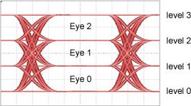
The ability to adjust the amplitude of PAM4 levels requires the Research and Development Package License.