Linearity
 Click Linearity on Eye Mode's PAM toolbar to activate one of three types of Linearity measurements. Linearity is a measure of the variance in amplitude separation (distribution) between the different PAM4, PAM6, or PAM8 levels. The linearity ratio is always equal to or less than 1.0. The value 1.0 indicates that the separations between all levels are equal. For non-compliant measurements, you can use a PRBS signal. For compliant measurements, you will need to use compliance linearity pattern that is called out in the relevant standard.
After click Linearity, the Linearity Select Measurement Setting dialog opens where you select the type of linearity measurement as shown in the following table.
| Available Measurement Definitions | :MEAS:EYE:PAM:LIN:DEF
SCPI Command Argument |
Compatible Waveforms | |||
|---|---|---|---|---|---|
| NRZ | PAM4 | PAM6 | PAM8 | ||
| RLM (Ratio Level Mismatch) (IEEE 802.3 Annex 120D). | RLMA120
|
● | ● | ||
| RLM (Ratio Level Mismatch) (IEEE 802.3 Clause 94). This is the default setting. | RLMC94
|
● | ● | ● | ● |
| Eye Linearity (CEI 4.0) | EYE
|
● | ● | ● | ● |
The measurement algorithms used for the linearity measurements in Oscilloscope mode, Eye mode, and Jitter mode are the identical. However, between these modes the measurement results yield small differences as the waveform data is represented differently. For example, in oscilloscope mode measurement are made at the center of individual UIs while eye mode measurements are made on the center of all acquired UIs at once.
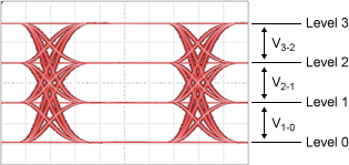
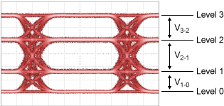
| Good Linearity | Poor Linearity |
|---|---|
| V3-2 = V2-1 = V1-0 | V3-2 ≠ V2-1 ≠ V1-0 |
|
|
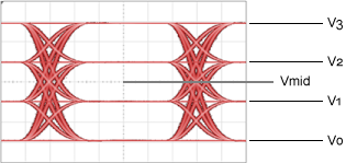
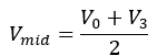
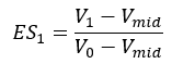
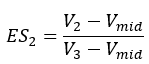
RLM IEEE 802.3 Annex 120D Measurement
The linearity is defined as a function of the mean signal level transmitted for each PAM4/6/8 symbol level. The following picture identifies for PAM4 the voltage levels used in the following equations. In the following equations, the term ES stands for the Effective Symbol Level.

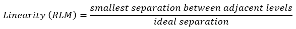
RLM IEEE 802.3 Clause 94 Measurement
PAM4 linearity is measured as:
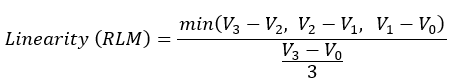
If the four levels measurements are the following values:
- L3 = 14.6 mV
- L2 = 7.5 mV
- L1 = –8.0 mV
- L0 = –15.2 mV
then, the linearity will be 0.715 as given by:

| Setting | Description |
|---|---|
| PAM-N Analysis Setup Dialog Settings | |
| Receiver Sample Timing | Configures the timing for sampling the signal data for all PAM measurements in Eye/Mask mode. |
| Eye Center Location | Selects the basis for determining the location of an eye's center on the waveform: at maximum eye width or maximum eye height. |
| Eye Level Width | Defines the timespan (in percentage of symbol width) over which an eye's amplitude level is measured. |
| Time of Level | Specifies the method used to locate the time at which to measure an eye's level. |
Measurement Algorithm
- An autoscale is performed to determine if the signal is formatted as PAM4, PAM6, PAM8, or NRZ.
- Determine the approximate signal-level amplitudes.
- Locate the crossing (transition) regions on both sides of the eyes.
- Determine the symbol period.
- Find the center of each eye. Note that the Receiver Sample Timing setting determines if only the middle eye (Eye 1/2) is located or if all three eyes are located (Eyes 0/1, 1/2, and 2/3).
- If the Eye Center Location setting is set to Maximum Eye Width, determine the horizontal line (center amplitude) across the eye at the maximum eye width and find the time at the line's midpoint (center time).
- If the Eye Center Location setting is set to Maximum Eye Height, determine the vertical line (center time) across the eye at the maximum eye height and find the amplitude at the line's midpoint (center amplitude).
- Perform the Levels RMS ("thickness") and Levels measurement for all eye levels:
- If the Time of Level setting is set to Eye Center, the following rules are used to determine the time location for measuring each level. At each time level, a vertical measurement "window" is centered and the RMS value of the eye's level is measured over this window. The amplitude at the RMS value gives the amplitude of each level. The width of the level measurement window is determined by the Eye Level Width percentage setting which is a percentage of the symbol period.
- If the Time of Level setting is set to Minimum RMS, the levels are measured by stepping a vertical measurement "window" in time across the entire symbol period and at each position measuring the RMS value (thickness) of each level. For each level, the minimum RMS value is selected. The amplitude at the RMS value gives the amplitude of each level. The width of the level measurement window is determined by the Eye Level Width percentage setting which is a percentage of the symbol period. For example, if the window is 25%, the symbol period is divided into four vertical measurement widows. The Eye Level Width setting can range from 1% to 25%. Generally, select a small percentage for measuring signals with poor quality eyes and a large percentage for good quality eyes.
- The Levels measurements derived in the previous step are placed in the linearity equation.
| Time Locations | PAM Waveform Levels and Eyes |
|---|---|
| Level 3: Center time of Eye 2/3. |
|
| Level 2: Average time of Eye 2/3's center time and Eye 1/2's center time. | |
| Level 1: Average time of Eye 1/2's center time and Eye 0/1's center time. | |
| Level 0: Center time of Eye 0/1. |
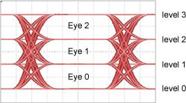
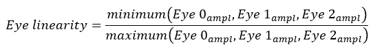
Eye Linearity (CEI 4.0) Measurement
Eye linearity is the ratio of minimum eye amplitudes (in Volts) to maximum eye amplitudes (in Volts).
SCPI Command
:MEASure:EYE:PAM:LINearity