PAM Linearity
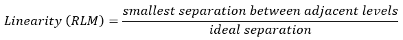
 Click Linearity on Oscilloscope Mode's PAM toolbar to activate one of three types of Linearity measurements. Linearity is a measure of the variance in amplitude separation (distribution) between the different PAM4 levels. The linearity ratio is always equal to or less than 1.0. The value 1.0 indicates that the separations between all levels are equal. For non-compliant measurements, you can use a PRBS signal. For compliant measurements, you will need to use compliance linearity pattern that is called out in the relevant standard.
After selecting Linearity, the Linearity Select Measurement Setting dialog opens where you select the type of linearity measurement:
- RLM (Ratio Level Mismatch) (IEEE 802.3 Annex 120D). Shown in Results table as RLM (A_120D).
- RLM (Ratio Level Mismatch) (IEEE 802.3 Clause 94). Shown in Results table as RLM (CL_94).
- Eye Linearity (CEI 4.0). Shown in Results table as Eye Linearity.
The measurement algoritms used for the linearity measurements in Oscilloscope mode, Eye mode, and Jitter mode are the identical. However, between these modes the measurement results yield small differences as the waveform data is represended differently within each instrument mode. For example, in oscilloscope mode measurement are made at the center of individual UIs while eye mode measurements are made on the center of all acquired UIs at once.
The PAM4 waveform must be displayed as a single-valued waveform. To accomplish this, turn pattern lock on using the :TRIGger:PLOCk command. On an N1000A, this requires instrument Option PLK.
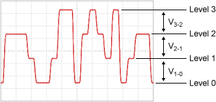
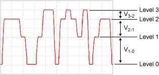
| Good Linearity | Poor Linearity |
|---|---|
| V3-2 = V2-1 = V1-0 | V3-2 ≠ V2-1 ≠ V1-0 |
|
|
RML IEEE 802.3 Annex 120D Measurement
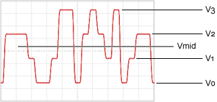
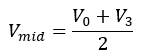
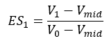
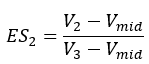
The linearity is defined as a function of the mean signal level transmitted for each PAM4 symbol level. The following picture identifies the voltage levels used in the following equations. In the following equations, the term ES stands for the Effective Symbol Level.

RML IEEE 802.3 Clause 94 Measurement
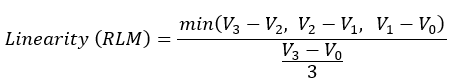
If the four levels measurements are the following values:
- L3 = 14.6 mV
- L2 = 7.5 mV
- L1 = –8.0 mV
- L0 = –15.2 mV
then, the linearity will be 0.715 as given by:

Eye Linearity (CEI 4.0) Measurement
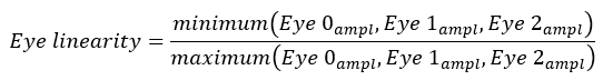
Eye linearity is the ratio of minimum eye amplitudes (in Volts) to maximum eye amplitudes (in Volts).
Setting the Timespan
You must turn pattern lock on, and set the timespan wide enough so that each logic level is visible on the screen. This would be four levels (0, 1, 2, 3) for a PAM4 signal. Failure to set the timespan wide enough results in an error. Consider the following items when setting the timespan:
- If multiple identical levels are displayed, the level that is present for the longest time will be selected for measurement. For example, if two logic levels are shown on the waveform, with one being 100 ps and the other being 150 ps, the 150 ps level is selected to be measured.
- To be considered a measureable level, the level must include at least 50% of the leading and trailing edges.
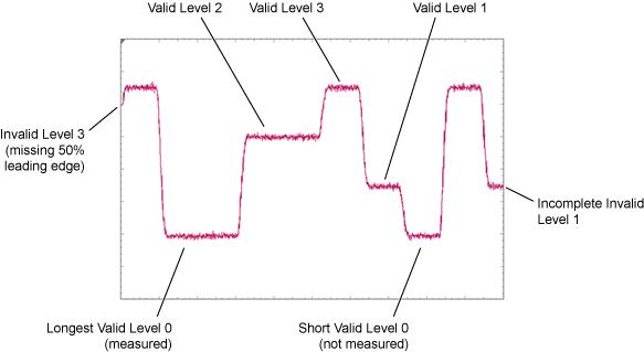
If the timespan is too narrow, the measurement results panel displays Region? or Level? instead of a measured value. Increase the timespan.
SCPI Command
:MEASure:OSCilloscope:PAM:LINearity