54753A Single-Ended TDR/TDT Module
Starting with firmware release A.06.90, 86100D Compatibility mode is no longer being actively tested and supported.
The minimum required 86100-series firmware version for this module is A.01.00.
The 54753A TDR/TDT plug-in module provide both time domain reflectometry (TDR) and time domain transmission (TDT) measurements. The module contains a built-in TDR step generator that launches a fast voltage step into the device under test. You can then monitor both the transmitted and reflected pulse at a particular point on the line. The instrument reveals the following information about the device under test:
- characteristic impedance
- position of any discontinuities
- type (resistive, inductive, or capacitive) of discontinuities
- type of loss (series or shunt)
The input circuits of the 54753A and 54754A can be damaged by electrostatic discharge (ESD). Therefore, avoid applying static discharges to the front-panel input connectors. Before connecting any coaxial cable to the connectors, momentarily short the center and outer conductors of the cable together. Avoid touching the front-panel input connectors without first touching the frame of the instrument. Be sure the instrument is properly earth-grounded to prevent buildup of static charge.
Using the 54753A TDR/TDT module gives more meaningful information concerning the broadband response of a transmission system than any other measuring technique. The addition of the second vertical channel provides capability of performing single-ended TDT measurements as well as TDR measurements. This module provides:
- automatic and manual single-ended TDR and TDT measurement capability
- user-selectable 12.4 or 18 GHz bandwidth (Channel 1 or 3)
- user-selectable 12.4 or 20 GHz bandwidth (Channel 2 or 4)
- 2.5 GHz bandwidth trigger channel
On the module's front-panel, the connector labeled Channel 1/3 identifies Channel 1 if the module is installed in the left slot and Channel 3 if the module is installed in the right slot. Channel 2/4 also refers to left and right slot channel identification.
See Also
- Available Accessories
- Modules
Protecting Input Channels
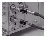
 The Keysight N9355CK01 is a DC coupled limiter (DC to 26.5 GHz) that is used to protect sensitive oscilloscope channels from damage due to electric overload stress (EOS) and electrostatic discharge (ESD). For example, voltages in excess of ±2V can damage high-performance samplers used in oscilloscopes. The limiter dramatically reduces the likelihood that such voltages will reach the sensitive part of the instrument, ensuring that the oscilloscope will perform reliably. Instruments with dual electrical channels, such as the 54754A, will require two N9355CK01 limiters. Step generators within the TDR modules use
≤0.2V, which is less than the diode threshold of the N9355CK01 limiter. The N9355CK01 can also be used to protect the electrical channel of the 86105x and similar modules, as long as the signal does not exceed –0.5V to +0.5V. The N9355CK01's voltage drop is ±0.6V to 0.7V at ±10 mADC.
The N9355CK01 will protect instruments from occasional and short voltage spikes. A major power source, such as a high voltage and current supply can still cause severe damage to the limiter itself, or the instruments. Operators should continue using industry standard EOS and ESD practices to minimize this risk.
Figure. Two N9355CK01s Inserted into TDR Module Signal Paths

Supplied Accessories
| Item | Description |
|---|---|
| 1810-0118 | SMA 50 ohm termination |
| 5061-5311 | APC 3.5 (f-f) adapter/connector saver (2) |
| 9300-1484 | Static safe kit |