Default Setup
On FlexDCA, click Setup > Default Setup to return the FlexDCA to a known start-up state. To set FlexDCA to its factory preset condition, click Setup > Factory Preset. You may find it helpful to use the default settings when initially setting up FlexDCA to view signals or to troubleshoot unexpected instrument behavior. The default settings are listed in the following table.
On a N1000A, press Default Setup to return the instrument to its factory default conditions. The instrument saves all customized settings in a file, which you can reload.
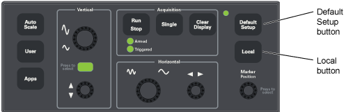
When a N1000A is remotely controlled, the Local button and ON/Standby switch are the only active front-panel controls. Press Local to return control of the instrument to the front panel. On FlexDCA, click Tools > Virtual Front Panel and click Local.
Because the settings of DCA-M extended modules are configured within FlexDCA, a default setup also returns DCA-M products to their default settings.
| Feature | Setting |
|---|---|
| Mode of Operation | Oscilloscope Mode |
| Acquisition | |
| Run/Stop | Run |
| Smoothing | None |
| Number of Averages | 16 (range: 2 to 32,768) |
| Base Measurement Configuration | |
| Top-base Definition | Auto |
| Thresholds | 10%, 50%, 90% |
| Eye Boundary 1 | 40% for NRZ eyes (Range: 0—100%) |
| Eye Boundary 2 | 60% for NRZ eyes (Range: 0—100%) |
| Channels | |
| Signal Type | Automatically detected. NRZ, PAM4, PAM6, or PAM8. |
| Display | Lowest numbered installed channel is on, all other channels are off |
| Bandwidth | Dependent on type of installed module |
| Scale | Dependent on type of installed module |
| Offset | 0V or 0W (Dependent on type of installed module) |
| Units | Volts (or Watts) (Dependent on type of installed module) |
| Display | |
| Persistence | Variable (Oscilloscope mode) Gray Scale (Eye/Mask mode) |
| Persistence Time | 300 ms, variable persistence (Range: 100 ms to 40s) |
| Grid | On |
| Grid Intensity | 100% (Range: 0 to 100) |
| Colors | Default color legend |
| UI Color Theme | not changed |
| Dialog Size | not changed |
| Dialog Opacity | not changed |
| Dialog Transparent Background | off |
| Mode Switch Animation | not changed |
| Connect Waveform Dots | Off |
| Histograms | |
| Mode | Off |
| Placement | Left |
| Window source | First available channel |
| Scale | Linear |
| Horizontal (Time Base) | |
| Scale | 20 ps/div 1 ns/div (86100C) |
| Delay from Trigger | 24 ns |
| Reference | Left |
| Units | Time |
| Jitter Mode Measurement Configuration | |
| Jitter Mode Graph | Histogram: Y Axis Linear Bathtub Scale: BER Layout: Quad |
| Jitter Mode Measurements | Units: Seconds Signal type: Auto Detect Results based on: Both Edges Sampling Level: 50% TJ Measurement BER: 1.0E-12 RJ Stabilization: off RJ Compensation: off |
| Jitter Mode Amplitude Measurements | Measurement Location: 50% Graphs based on: Both Edges One/Zero Level Definition: Average Units: Volts or Watts RIN Relative to: One Level RIN Normatilization: Decibel TI Measurement BER: 1.0E-12 RN Stabilization: off RN Compensation: off |
| Limit test | Off |
| Markers | Off |
| Mask Test Measurement Configuration | |
| Mask test | Off |
| Alignment Method | NRZ Eye |
| Alignment Timing | Once |
| Mask Scale Mode | X and Y |
| Y-Axis Mask Align Measurement Area | Eye Boundaries (Align to One, Zero Levels) |
| Trigger | |
| Source | Front Panel |
| Hysteresis | Normal |
| Slope | Rising Edge |
| Bandwidth | Clock Trigger (50 MHz - 32 GHz) |
| Waveform Memory | |
| Memory Display | All Off |
| Waveform Source | First available channel or Memory 1 |
| Waveform Signal Processing | Current function deleted |