DFE Operator (Advanced)
The Advanced tab lets you Specify Pattern Symbol Sequence and enter the input signal's pattern, the equalizer's Clock Delay, Tap Limits, and Threshold Bandwidth.
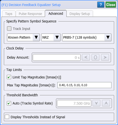
Specify Pattern Symbol Sequence
Use these settings to specify input waveform's pattern symbol sequence (NRZ or PAM4). You can select to have the pattern automatically detected (default), select from a know standard Known Pattern, or a BERT Pattern File (*.ptrn). Available known patterns are listed in the following table. If you select to import a Pattern File, you can specify if the pattern uses Gray Coding. Gray coding, or reflected binary code, is a coding pattern where successive symbols differ by one binary bit. For example in the case of PAM4, binary bit sequences 00, 01,10, and 11 represent levels 0, 1, 2, and 3.
DFE Operator Presets
- IEEE 802.3ck
Clock Delay
Clock Delay to delay the decision point used by the slicer. The decision point is placed directly between the edges, so the edges are delayed by the same amount. The Clock Delay is specified in seconds.
Tap Limits
Tap Limits can be selected as based on maximum, bbmax(n), and minimum, bbmin(n), tap values tap. If the Use Pulse Response Optimization) setting in the dialog's Taps tab is on, you can also select Limit Tap Magnitudes and enter a string of comma separated maximum tap magnitudes, bmax(n).
Threshold Bandwidth
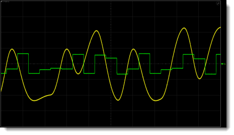
Enter the Threshold Bandwidth to set the cutoff frequency of the Gaussian filter. Auto sets the cutoff frequency equal to the symbol rate. You can also select to Display Thresholds Instead of Signal. This allows you to view the way a hardware DFE works by varying the slicer threshold. The waveform viewed is labeled Operator Threshold Waveform in the Block Diagram of Hardware DFE in this topic.
| DFE Input Waveform | DFE Output Waveform |
|---|---|
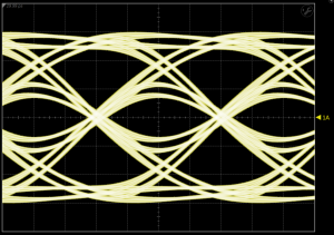
|
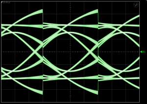
|
Waveform Shown in Oscilloscope Mode
with "Display Thresholds Instead of Signal" Selected