Calibration System
Use the System tab to setup automatic DCA-M module calibrations (based on elapsed time and temperature change) and the Optical Calibration tab to perform full or partial optical path calibrations. The optical calibration calibrates every possible optical path from the fixture lanes through the optical switch to DCA-M modules.
| Dialog Tab | Hardware Diagram | Sessions |
|---|---|---|
| System | • | |
| DCA-M module | • | |
| Optical Calibration | • | • |

Automatic Instrument DCA-M Calibration
Use the Instrument AutoCal feature to calibrate all connected DCA-M modules for the current temperature and time. You can set the Maximum Elapsed Time or Maximum Temperature Change that would automatically run the calibration. Click Run AutoCal Now to start the calibration regardless of the elapsed time or temperature change.
The current configuration does not support AutoCal
If "The current configuration does not support AutoCal" message is displayed in the dialog System tab as shown in the above picture, switch hardware is preventing the AutoCal from being performed. AutoCal requires that the optical switch supports being configured by FlexOTO to disconnect all switch paths to the switch's output. Otherwise, an AutoCal is not possible. As a results Keysight N773xx-series switches do not support AutoCal. Other switches may support AutoCal based on their installed switch modules. If you have installed a switch by writing a switch driver, the driver must by able to send to the switch the required commands to disconnect all switch paths. Click Details to discover the optical paths that do not have a disconnected state.
If this message is displayed, the solution is to disconnect the cables from the module and perform a module calibration using the FlexDCA application.
Optical Calibration
Click New Calibration to perform a new calibration. Click Browse to open an existing calibration. During the optical calibration, every path shown in the Hardware Diagram is calibrated using an optical source that you provide. The power of the optical calibration signal must be within the following range: 100 μW ≤ average power ≤ 2 mW. The Optical Calibration is designed to minimize the need to change port connections during the calibration.
If the Hardware Diagram has not been created or is invalid, the New Calibration button will not be active.
Click Browse to load a previously saved calibration file into FlexOTO. Calibration file include calibration data for each optical path, DCA-M module model and serial numbers, switch group names, as well as user names (Fixtures Demuxes, and Impairments). If the information in the calibration file does not match the current Hardware Diagram, a warning will be displayed. For example, "Missing module". To learn more information about the reason for the failure, click Details in the Calibrations dialog.
When the optical calibration is active, all loss due the following items (excluding any specified nominal attenuation) will be removed from the relevant measurements:
- Connected switch paths.
- All of a demultiplexer's lane paths.
- All impairment paths.
To include the nominal attenuation of demultiplexers and impairments in FlexOTO's measurements, enter the nominal attenuation by clicking on the Demux Setup and Impairments Setup blocks on the Hardware Diagram.
To perform the optical path calibration
- Click New Calibration. Or, click Browse to open an existing calibration for which you want to enter new calibration data for all or a selected number of optical paths.
- In the Optical Calibration dialog shown below, enter the Average Optical Power of the calibration signal that is input to the selected path. Use an optical power meter or DCA-X oscilloscope to measure the average optical power of the optical source. The average optical power must be between 100 μW and 5.000 mW. After the calibration starts, you can enter a new value for each path.
- Enter the Maximum Allowed Path Attenuation. The entered attenuation can range from 3.0 dB to 30.0 dB. A message is displayed if attenuation exceeds this setting.
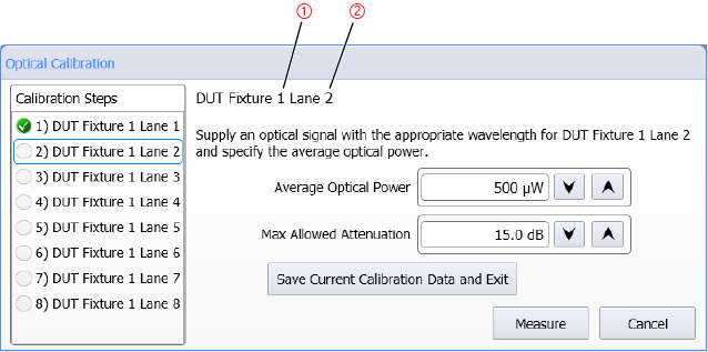
- Click Measure to begin the calibration. The Optical Calibration dialog guides you in connecting the power source to the correct switch port. For each path, an optical source (the calibration reference) must be connected to the Fixture and Lane as identified as items 1 and 2 in the figure below.
- When the calibration completes, a calibration is saved in the user folder (C:\Users\name\Documents\Keysight\FlexOTO\Optical Calibrations). The file name is in the form of OpticalCalibration_YYYY-MM-DD_N.ocdx. If you want to give your calibration file a custom name, click Browse and enter a new filename.

Partial Calibrations
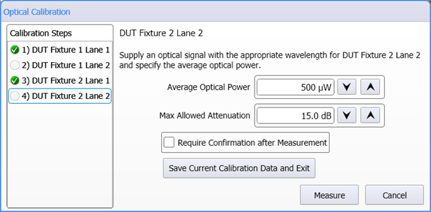
Optical path calibrations are very flexible. In the Optical Calibration dialog, you can randomly click (select) any listed path to calibrate or recalibrate the path. You can also perform and save a partial calibration as shown in the following picture. If your measured attenuation for any of the paths exceeds the specified Max Allowed Attenuation setting, the Confirm button is displayed. Click it to accept the measured attenuation or click Measure to repeat the measurement.

Require Confirmation After Measurement
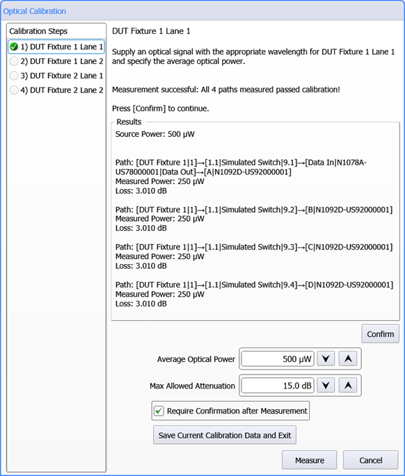
The Require Confirmation After Measurement setting allows you to pause the path calibration on a path to view the calibration results. You can click Confirm to accept the calibration or, if an error occurs, click either Cancel to abandon the calibration, Confirm to use the current questionable results, or Save Current Calibration Data and Exit to save a partial calibration.
