DUT Types, Test Setups, and Tips!
This topic provides a list of useful tips, gathered in one place, to help you to quickly master FlexPLL measurements.
Source and Receiver Symbol Rate Settings (Type of DUT)
Depending on the type of DUT, the DUT's input and output rates and waveform types can greatly vary, and you must set the System Setup dialog's settings according to your DUT's demands and the type of Source instrument that you are using.
Some dialogs enter the signal rate using frequency (Hz), and some use Symbol rate (baud or Bd) based on the type of signal. A clock or data signal's rate can be expressed as a frequency (Hz) or symbol rate (baud, Bd). Although technically a clock is used for timing and does not transmit information symbols, a clock is often expressed as an equivalent symbol rate. For example, a 125 MHz clock has two states (symbols) per period: high and low. Thus, the clock's symbol rate is twice its frequency, 250 MBd.
Example of Setting Changes Between Calibration and Measurements
These two tables demonstrate how FlexPLL settings need to be changed between the test setup calibration and measurements. These settings were used to test a PCIe 4.0 (Gen 4) Device Under Test (DUT).
Notice in this table, where an 81150 or 81160 source is used, that the source Wave Type is Clock. This source does not have a data selection.
| Settings | During Calibration | During Measurement |
|---|---|---|
| Source Wave Type | Clock | Clock |
| Clock Rate | 100 MHz | 100 MHz |
| CDR Setup Symbol Rate | 400 MBd | 16 GBd |
| CDR Setup Loop BW | 100 KHz | 160 KHz |
Notice in this next table, where an M8000 source is used, that the source Wave Type is changed from Data to Clock between the calibration and the measurements. During the calibration, the DUT is not in the setup and the source is connected directly to the Receiver's input.
| Settings | During Calibration | During Measurement |
|---|---|---|
| Pattern | PRBS7 | PRBS7 |
| Source Wave Type | Data | Clock |
| System Clock Rate | 16 GBd | 16 GBd |
| Clock Rate | 100 MHz | 100 MHz |
| CDR Setup Symbol Rate | 16 GBd | 16 GBd |
| CDR Setup Loop BW | 160 KHz | 160 KHz |
Example Test Setups
Figure 1 shows the example of a clock-recovery DUT that outputs a 1:2 sub-rate clock.
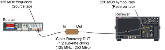
The correct dialog settings for Figure 1:
- Source tab's Symbol Rate:
125 MHz - Receiver tab's Symbol Rate:
250 MBd
Figure 2 shows the example of a clock-recovery DUT that outputs a 2:1 super-rate clock.
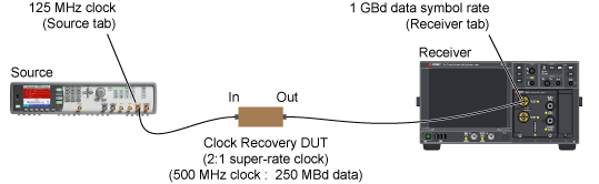
The correct dialog settings for Figure 2:
- Source tab's Symbol Rate:
125 MHz - Receiver tab's Symbol Rate:
1 GBd
Source and Receiver Symbol Rate Settings (Calibration vs Measurements)
During the test setup calibration, the source's output is directly connected to the receiver's input, and there is no DUT in the test setup. The frequency (or signal rate) is set to the value that is intended as the input to the DUT. For this example, Figure 3 shows a calibration setup using 125 MHz (250 MBd).
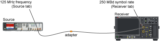
The correct dialog settings during calibration:
- Source tab's Symbol Rate:
125 MHz - Receiver tab's Symbol Rate:
250 MBd
After the calibration, the DUT is inserted in the test setup as shown in Figure 4. In this example, the DUT recovers the clock at a 2:1 super rate. So, the 250 MBd symbol rate input results in a 500 MHz clock (1 GBd symbol rate) at the receiver's input.
When the calibration completes, you should:
- Insert the DUT in the test setup.
- Open the System Setup dialog's Receiver tab and enter the following correct symbol rate. For this example, the correct symbol rate is:
- Receiver tab's Symbol Rate:
1 GBd - Click the Lock button in the dialog to lock the receiver's clock recovery to the correct symbol rate.
You can record the Source and Receiver tab settings in a Preset. Create one preset for calibration settings and another preset for settings with the DUT inserted. Using Preset can reduce setup time and avoid the need to remember specific signal values for different DUTs.
When a Preset is created in the System Setup dialog, the Preset includes the configuration settings from the Source, Receiver, and Acquisition dialog tabs. It does not matter in which of these three tabs that you create or import the preset.
During the response calibration, FlexPLL does not lock the receiver's clock recovery as locking is not required for a valid calibration. However, after a Response calibration, FlexPLL automatically locks the receiver's clock recovery for measurements.
When the source is an 81160A, the source signal is always a square wave. However, if the source is a supported M8000-series BERT or M8199A AWG, you have the option to select the Source signal to be either a clock or a data signal.
Avoid Directly Changing Source and Receiver Settings
Always use FlexPLL's Source Setup and Receiver Setup dialogs to make the setting changes that are listed in these FlexPLL dialogs. Avoid changing these settings on the actual source or receiver instrument as FlexPLL will automatically cancel them. For FlexPLL settings that are not available in these dialogs (not under FlexPLL control), you can make these settings directly by using the following steps:
- In FlexPLL's Source Setup or Receiver Setup dialogs, click Disconnect.
- On the source or receiver, make your changes. For example, you can turn the receiver's channels on and view the input channel's waveform during testing.
- After making your changes, click FlexPLL's Connect button to re-establish FlexPLL's control.
If you changed a DCA-X or DCA-M setting that is under FlexPLL control, for example CDR symbol rate, FlexPLL overwrites the setting when re-connecting.
FlexPLL continuously monitors DCA-X. If you click Local on DCA-X to view or change a setting, FlexPLL will, within a few seconds, automatically return DCA-X to remote control.
Miscellaneous
- A Response calibration always results in a saved calibration data file, which can be reloaded into FlexPLL.
- When connecting the RF cable between the source's output and the DUT's input, be aware that some PCI Express devices do not include an "on board" termination. In this case, connect a 6 dB matching attenuator on the output of the source.
- If FlexPLL is running on the DCA-X, FlexPLL may hide the FlexDCA application. If a keyboard is attached, press Alt-Tab to switch between applications.