Creating a Limit Test
The following shows the steps for creating a Limit Test using the simulated hardware preset signal.
- Select to display the Limit Tests Dialog Box. Once tests have been created, they will be listed here.
- Click to create a new test in the Limit Test Editor Dialog Box.
- In the Name box, enter as the name of the limit test. Once limit lines have been defined, they will be listed here.
- Click to create a new limit line in the Limit Line Editor Dialog Box. This dialog box consists of 3 tabs, each used to define a part of the limit line.
- In the Name box, enter as the name of the limit line to be created. The check box defaults to enabled. We are defining a upper limit with no margin, connecting the points and having the trace fail in a fail color. These are default parameters. For more information on these parameters, see Line Tab.
- Select the Units tab. We want the limit line to be in the frequency domain with a Y Format of log (dB) and Y Unit of auto. The X and Y References are absolute. These are default parameters. For more information on these parameters, see Units Tab.
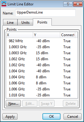
- Select the Points tab and click New to display the Limit Point Editor Dialog Box.
-
Enter 982 and select MHz Megahertz: A unit of frequency equal to one million hertz or cycles per second.. (If a "m" is entered after the number, MHz will be implied.) Enter -40 (dBm deciBels referenced to a milliWatt: dB relative to 1 milliwatt dissipated in the nominal input impedance of the analyzer is implied). Connect from previous point check box is enabled. Click OK or Enter. Our first point will be listed in the Points Tab of the Limit Line Editor.
If editing an existing that is displayed on a trace, simply click and the changes to the point will automatically be applied and saved. -
Click and create each of the following points:
1.0003GHz and -35dBm
1.0003GHz and 15dBm
1.002GHz and 15dBm
1.002GHz and -40dBm
1.004GHz and -40dBm
1.004GHz and 8dBm
1.006GHz and 8dBm
1.006GHz and -35dBm
1.018GHz and -35dBm
-
Click OK until out of the Limit Tests area.
-
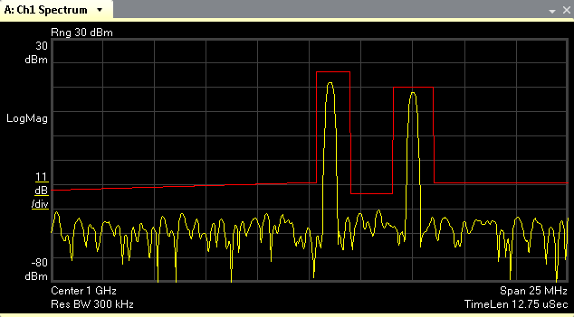
Select Markers > Limits to display the Limits Tab dialog box. Select Demo. This will display the Demo Limit Test on the active trace.
See Also