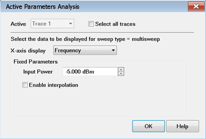
Option 110 Measurement Parameters
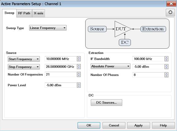
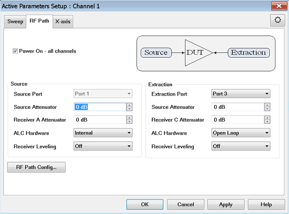
Note: In
the example below, Port 1 is the Source Port (DUT input) and Port
3 is the Extraction Port (DUT output). Port 3 or Port 2 can be
chosen as the output of the DUT.
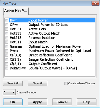
Option 111 Measurement Parameters
IPwr
Check to measure input
power.
OPwr Check
to measure output power.
HotS31 Check
to measure Active Gain.
HotS33 Check
to measure Active Output Match.
HotS13 Check
to measure Reverse Isolation.
HotS11 Check
to measure Active Input Match.
Gamma Check
to measure optimized Gamma.
Pmax Check
to measure maximum delivered power.
Xs(3,3), Direct
Reflection Coefficient. The fundamental XS33
parameter
which is used, in combination with XT22, to describe the change
in b2
as
a function of a2, the signal reflected
from the load.
Xt(3,3), Direct
Reflection Coefficient. The fundamental XT33 parameter which is used,
in combination with XS22 to describe the change
in b2 as
a function of a2, the signal reflected
from the load.
Xf(3,1), Output
Coefficient. The fundamental XF31 parameter.
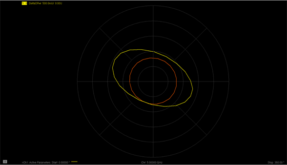
DeltaOPwr Check
to measure the delta between the output wave and output power
to Z0 load.
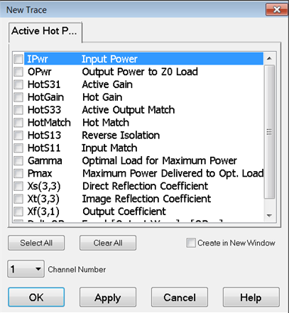
Available
for option 111 only (the following traces are not restricted to
50 GHz)
HotGain Check to measure
forward gain using linear S-parameters output/input.
HotMatch Check to measure
active output match using linear S-parameters.
Buttons
Select All Click
to select all measurement parameters.
Clear All
Click to deselect all measurement parameters.
Create in New Window Check to create a new trace in a
new window for the measurement.
Channel Number Select
a channel number for the measurement.
|

 ).
). ).
). ).
).