Intermodulation Spectrum measurements can be made independently, or coupled with Swept IMD measurements. They are a distinct measurement class. Therefore, IM Spectrum measurements are always made in a separate channel.
The following VNA features are NOT available in an IM Spectrum channel:
Unratioed receiver measurements (A, B, R)
Save Formatted Citifile data.
External Test Set Control (Option S93551A/B)
An IM Spectrum channel can be created independently from a Swept IMD channel or coupled with the stimulus settings of an existing Swept IMD measurement.
Press Meas > S-Param > Meas Class....
Select IM Spectrum, then either:
OK delete the existing measurement, or
New Channel to create the measurement in a new channel.
With a Swept IMD channel active, press Marker on the front panel.
Move the marker to the data point of interest. It can be moved later.
Press Marker > Marker Functions > Marker -> IM Spectrum.
This creates or configures an existing IM Spectrum channel based upon the configuration of the Swept IMD channel.
To perform this function remotely:Execute the VBScript file located on the VNA.
Notes:
|
How to add IM Spectrum traces With the IM Spectrum channel active and a Tr1 Output trace displayed: |
|
Using Hardkey/SoftTab/Softkey |
Using a mouse |
|
|
Choose from:
|
How to start the IM Spectrum Setup dialogWith an IM Spectrum measurement active: |
|
Using Hardkey/SoftTab/Softkey |
Using a mouse |
|
|
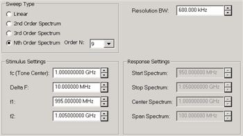
Note: The number of data points in an IM Spectrum channel = 3 * SPAN / ResBW. This can NOT be changed directly. Configures the Sweep Type and frequency range for IM Spectrum measurements. Sweep TypeProvides several methods to tune the IM Spectrum receivers (NOT stimulus) to view the power spectrum of arbitrary frequency ranges or various distortion products. Linear Allows the start/stop or center/span receiver frequencies to be set arbitrarily for f1 and f2. Enter the Response Settings below. 2nd Order Couples the receiver frequency range to f1 and f2 to provide a convenient means of observing the spectrum surrounding ONLY the high-side 2nd order harmonic where Center = (f1 + f2), Span = 3 * (f2 – f1). Note: The center frequency is NOT set on the main tones. 3rd Order Couples receiver frequency range to f1 and f2 to provide a convenient means of observing the spectrum surround the main-tones including the 3rd Order products where Center = (f1 + f2) / 2, Span = 4 * (f2 – f1). Nth Order Couples receiver frequency range to f1 and f2, providing a convenient means of observing the spectrum surrounding the main-tones for an arbitrary span where Center = (f1 + f2) / 2, and Span = N * (f2 – f1). This allows you to set the span arbitrarily, but have the center frequency track the main tone frequencies. Resolution BWThe IM Spectrum channel utilizes a set of Gaussian filters instead of the standard VNA IF filters in order to provide similar behavior to traditional spectrum analyzers. The comprehensive list of filters that are available for IM spectrum are: 3 MHz, 1 MHz, 600 kHz, 300 kHz, 150 kHz, 100 kHz, 60 kHz, 10 kHz, 3 kHz, and 1 kHz. Note: The 10 kHz Res BW filter can generate image signals which are not a product of the DUT. You can verify the integrity of a questionable signal by switching to the 3 kHz or 60 kHz filter and looking for the image signal in the same location. Not all of these filters are available for all measurements. Narrower filters are available for use with narrower frequency spans, and wider filters are available for wider spans. Stimulus SettingsAllows configuration of the main-tone frequencies. Available ONLY when Tracking is OFF.
Response SettingsAllows configuration of the frequency range to sweep the receivers in terms of start/stop or center/span. Available for Linear sweep types ONLY.
Note: The minimum Start Spectrum frequency that can be set is 40 MHz.
|
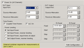
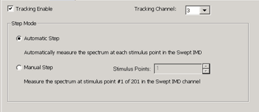
These selections are NOT available when there is no Swept IMD channel. Allows the IM Spectrum channel to use (track) the stimulus (Main Tone) settings of an existing Swept IMD channel. Tracking Enable Check to use the frequency and power stimulus settings from the specified IMD channel. When enabled, stimulus settings on the Frequency Tab are disabled and ALL stimulus settings, such as frequencies, power and attenuator settings, and calibration, are copied from the Swept IMD channel to the IM Spectrum channel.
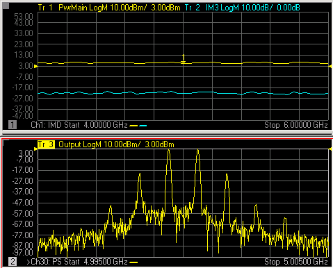
Step ModeWhen tracking is enabled, set the method by which the IM spectrum measurement tracks the IMD channel. Manual Step When selected, IM Spectrum measurements occur at only the specified IMD channel data point. Stimulus Point specifies the data point, by number, in the Swept IMD channel which has the stimulus settings to use for the IM Spectrum sweep. Automatic Step When selected, causes the IM Spectrum channel to sequentially setup each of the stimulus conditions through which the Swept IMD channel sweeps the DUT. Each sweep of IM Spectrum is performed using the next set of stimulus conditions. For example, in the above image, the first Swept IMD data point is at 4 GHz. The first IM Spectrum sweep uses a center frequency of 4 GHz. The following IM Spectrum sweep would be at the second Swept IMD data point or 4.01 GHz, and so forth. After the last data point in the sweep is reached, the IM Spectrum channel begins again at the first Swept IMD data point. The only indication that Tracking is enabled is in Automatic mode, you can see the center frequency increment with each IM Spectrum sweep.
|
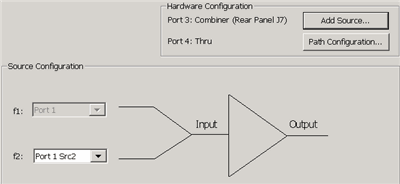
To accommodate single-source VNA models, an external source can be used for the RF2 tone. Learn how to configure an external source and combiner to make Swept IMD, IMDx, IM Spectrum, and IM Spectrum for Converters measurements. RF1 Always uses VNA internal source 1. RF2 Available for selection when an external source is configured and Active. Add Source Click to configure an external source using the External Source Configuration dialog. Path Configuration Click to launch the Path Configuration dialog (PNA-X models only). |
A calibration corrects the IM Spectrum source and receiver power level accuracy of the displayed Tones.
A calibration of the IM Spectrum channel is NOT performed using the Calibration wizard. An IM Spectrum channel is calibrated by applying a Cal Set in one of the following ways:
A cal that was used on a Swept IMD channel. The Cal Set can be applied to the IM Spectrum channel using the Manage Cal Sets dialog (Learn how) or from the Marker =>IM Spectrum softkey (Learn how). However, a Swept IMD channel with Sweep Type = Power Sweep can NOT be applied to a IM Spectrum channel. This is because a Cal Set for power sweep contains only a CW frequency and the IM Spectrum channel requires a swept frequency range. Zero Span is not supported in an IM Spectrum channel.
A Source Power and Receiver Cal Set from a standard channel calibration. This can be a full calibration, but must include a source power cal for the source port (1) and receiver cal for the B receiver. Only one source can be corrected. Learn how to apply a standard Cal Set.