VNA Source 2 for LO on 4-port models

Path Configurator - Default configuration on PNA-X option 423
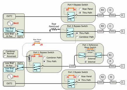
By default, Internal source2 (Src2) is supplied at ports 3 and 4.
Bypass switches must be in "Thru Path"
This topic discusses Noise Figure on Converters:
Mixer Frequency tab (separate topic)
Mixer Power tab (separate topic)
Mixer Setup tab (separate topic)
The following general information (contained in Noise Figure Application for Amplifiers) is also relevant for NFX measurements:
Noise Figure on Converters requires Noise Figure (Option 0pt 028 or 029 and S9x029A/B).
Learn more about Noise Figure requirements.
Upconverters OR downconverters ONLY (not both).
Image rejection is NOT provided in NFX.
The following VNA features are NOT available with NFX:
Analog Sweep (Stepped sweep mode only)
Independent IFBW, Power Levels, or Sweep Time in a segment table is NOT supported.
Log frequency sweeps
Save Formatted Citifile data.
Some Fixturing Features
External Test Set Control (Option S93551A/B)
Pulse measurements
Segmented sweeps (an alternative is to set up a separate channel for each frequency band)
Embedded LO measurements ARE supported in NFX. Learn more.
The PNA-X is extremely versatile, and can be configured in many ways to make NFX measurements. While not all conceivable configurations are documented here, a few of the most common examples are provided to show the basic concepts.
Learn more about connecting the DUT input and output to the VNA.
The DUT LO can be connected to an external source OR VNA internal second source (if available).
Select an LO Source on the Mixer Setup tab.
Note: Noise that is present on the LO source will be directly transferred to the DUT output. This noise can NOT be calibrated out of the noise measurement. Therefore, choose a low-noise source for the LO, such as an Keysight ESG or PSG, which is better than the VNA internal source.
External LO Source though Port 3 or Port 4 (4-port PNA-X only)
Connect the DUT LO to PNA-X Port 3 or Port 4.
Connect external source to rear-panel J7 (Rear-panel load on below diagram) for Port 3; J3 for Port 4.
For Port 3, NO switching is required.
For Port 4, switch Port 4 Bypass Switch to Rear Panel.
PNA-X Internal LO Source
SRC 2 Out 1 or Out 2 on front-panel or 2-port / 2-source PNA-X
Port 3 or Port 4 on 4-port PNA-X
VNA Source 2 for LO on 4-port models
|
Path Configurator - Default configuration on PNA-X option 423
|
Using the Noise Figure Application
Use the following general procedure to make measurement with the Noise Figure App:
For Opt 029 and H29, copy your Noise Source ENR file to the VNA C:\Program Files(x86)\Keysight\Network Analyzer\Noise folder.
Connect the DUT. Learn more.
Measure Noise Figure.
Optional Click File, then Save to save Noise Figure data in the following formats: (available ONLY when NF correction is ON.)
*.CTI Citifile
*.PRN
*.nco Noise Correlation Matrix data in S2P format. See Noise Model.
See Also: Measurement Tips
Connect the noise source to the 28V connector on the PNA-X rear panel. NOT required for Opt 028. The Noise Source is turned ON and OFF automatically as needed during a calibration. Connect the noise tuner to Port 2 reference place when prompted during calibration.
Connect the noise tuner (ECal module). NOT required for 50 GHz models and Scalar Noise Figure measurements.
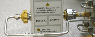
On the VNA front panel, remove the Port 1 jumper cable SOURCE OUT / CPLR THRU. Opt 028 allows Noise Figure measurements using any two VNA ports. Connect the noise tuner to the front-panel jumpers for the source (DUT input) port.
Connect M-F tuner (N4691B-M0F) using the supplied cable (N5242-20137) and adapter (85052-60013).
When using F-F ECal module (N4691B-00F), order a 3.5 mm M-M adapter (85052-60014).

On the VNA front panel, press Meas > S-Param > Meas Class....
Select Noise Figure Converters, then either:
OK delete the existing measurement, or
New Channel to create the measurement in a new channel.
A Noise Figure measurement is displayed. Do the following to add or change parameters to display.
The same Noise parameters that are available in the Noise Figure application are also available in the NFX application. Learn more.
In addition, the following Mixer and Raw Receiver parameters are available in an NFx channel:
SC21- Conversion Loss
SC12 - Reverse Conversion Loss
S11 - Input match
S22 - Output match
IPWR - Input power to mixer/converter. Same as R1 (Source1)
OPWR - Output power to mixer/converter. Same as B (Source1)
RevIPWR - Power applied to mixer/converter Output. Same as R2 (Source2)
RevOPWR - Power measured at mixer/converter Input. Same as A (Source2)
Specify a receiver to measure at LO1 frequencies with the notation:
<Receiver>LO1
For example: ALO1 or R1LO1
Specify a receiver to measure using a source port, with the notation:
<Receiver>_<source port>
For example: A_3 or R1_1
How to start the Noise Figure Setup dialog |
|
Using Hardkey/SoftTab/Softkey |
Using a mouse |
|
|
The following are the Valid Mixer Configurations:
Sweep Type |
Input |
LO |
Output |
Linear |
Swept |
Swept |
Fixed |
Swept |
Fixed |
Swept |
|
CW |
Fixed |
Fixed |
Fixed |
Fixed |
Swept |
Swept |
For determining a valid mixer configuration with 2 LOs, one Fixed LO and one Swept is equivalent to having a single-stage Swept LO.
If you create an invalid Sweep Type / Mixer Configuration, a red message appears like the following:
![]()
If this occurs, change the Sweep Type on the Frequency tab.
See other rules for configuring a mixer.
The following tabs are available on the NFX Setup dialog:
Mixer Frequency (separate topic)
Mixer Power (separate topic)
Mixer Setup (separate topic)
Sweep TypeLinear - Use for Swept Input parameters CW Frequency - Use for Fixed Input parameters X-Axis DisplayAnnotation: Select the frequency range to display on the X-axis. Sweep SettingsClick to learn more about these settings.
Learn about the Load/Save *.mxr files, and other buttons across the bottom of all NFX Setup tabs. |
Learn about the Load/Save *.mxr files, and other buttons across the bottom of all NFX Setup tabs. |
Learn about this and the Path Configuration dialog for the 50 GHz models. |
This dialog is identical to the Noise Figure Setup for amplifier EXCEPT for the following setting. Learn about the rest of this dialog. Enable Source Pulling for S-Parameters (For mixers with low reverse isolation). When checked, during S22 (output match) measurements, the noise tuner is switched to present different impedance states to the DUT input. From these measurements, S22 is computed as though the input is seeing a 50 ohm match. This requires more sweeps. Check this box when the converter has low reverse isolation, as is the case when the NO output path is NOT padded with attenuation. Otherwise, clear this checkbox as S22 measurements will not be improved. An accurate S22 measurement is essential when measuring S-parameters during an NFX calibration. Learn about the Load/Save *.mxr files, and other buttons across the bottom of all NFX Setup tabs. |
Mixer Frequency tab - NFX Setup -dialog box help |
|
Mixer (LO) Power tab - NFX Setup dialog box help |
|
Mixer Setup tab - NFX Setup dialog box help |
|