Mask Test
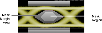
Mask testing lets you verify that a displayed waveform or real-time eye diagram complies with industry-standard definitions for electrical and optical waveforms. To comply with the industry standard, the input waveform must remain outside the shaded mask regions. As shown in the following picture, mask regions are shown in light gray. Mask margin regions are shown in dark gray. Data points that fall inside a mask region appears in red and are logged as a mask test failure.
Masks are similar to limit lines. Masks are typically applied to eye diagrams while limit lines are applied to single-valued waveforms. Masks (and limit lines) always display the pass / fail status which indicates if any data points have occurred outside of the boundaries.
You can apply limit testing to masks (and limit lines). Limit testing stops data acquisition based on broad range of acquisition, measurement, or data point conditions. Masks (and limit lines) are defined in ASCII XML files, which you can create using any text editor. However, masks require different XML elements as compared to limit lines.
Mask Test Operations
To add a mask test, view the results, change the test setup (in other words, to specify the mask test scaling, margins, or limits), or exit a mask test, see:
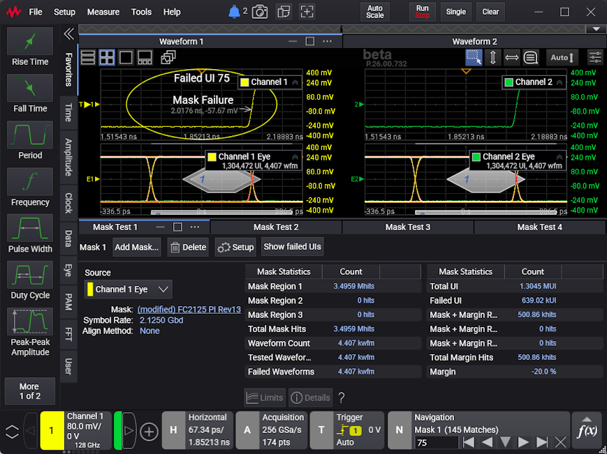
If there are failed UIs (which are recorded when scaling uses manual alignment) and acquisitions are stopped, you can use the Navigation controls to "unfold" a real-time eye and see where the failures occurred in the last acquired waveform. See Navigating Failed UIs.
Mutiple Mask Tests
You can apply parallel mask tests to multiple eye diagrams, which can save valuable test time on multi-lane devices. You can even apply more than one mask to the same eye diagram.