Trigger Setup
A trigger setup tells the oscilloscope when to acquire and display data. For example, you can set up to trigger on the rising edge of the analog channel 1 input signal.
You can use any input channel or the Aux Trig In input as the source for most trigger types.
You can adjust the vertical level used for analog channel edge detection by turning the Trigger Level knob. See Front Panel Trigger Controls.
In addition to the edge trigger type, you can also set up triggers on rise/fall times, patterns, pulse widths, runt pulses, setup and hold violations, and more. See Trigger Modes.
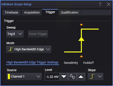
Trigger settings are accessed from the Trigger badge in the lower-right part of the user interface.
![]()
The Trigger badge also displays the trigger level and the trigger status (see Status).
As with all badges, you can select the upper middle part of the badge to open a pop-up menu that has controls for commonly used settings.
![]()
And, you can select the left shaded portion of the badge to open the full setup dialog box.
Changes to the trigger setup are applied immediately. If the oscilloscope is stopped when you change a trigger setup, the oscilloscope uses the new specification when you press [Run/Stop] or [Single]. If the oscilloscope is running when you change a trigger setup, it uses the new trigger definition when it starts the next acquisition. You can save trigger setups along with the oscilloscope setup.
Options that apply to all trigger types are:
-
Sweep — Select Auto to automatically trigger when the specified trigger condition has not occurred for some period of time. Select Trig'd to turn off automatic triggering. See Sweep (Mode).
-
Force Trigger — When triggers are not occurring, you can use ths button (or the [Force] front panel key) to trigger on anything, acquire, and display captured data.
-
Sequence — Lets you set up a trigger on an event that follows another event. See Sequence Triggers.
-
Sensitivity — These options include sensitivity and coupling (similar to analog input channel coupling but affecting the trigger input only) settings. See Sensitivity.
-
Holdoff — These options include holdoff settings. See Holdoff.
Triggers and Acquisition Memory
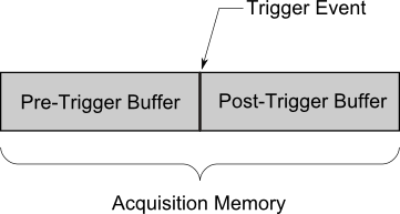
A triggered waveform is one in which the oscilloscope begins tracing (displaying) the waveform, from the left side of the display to the right, each time a particular trigger condition is met. This provides stable display of periodic signals such as sine waves and square waves, as well as nonperiodic signals such as serial data streams.
The figure below shows the conceptual representation of acquisition memory. You can think of the trigger event as dividing acquisition memory into a pre-trigger and post-trigger buffer. The position of the trigger event in acquisition memory is defined by the time reference point and the delay (horizontal position) setting (see Displayed Trigger Location).