External and Auxiliary Triggering


External and auxiliary triggering is used to synchronize the triggering of the analyzer with other equipment.

  1. Overview

  2. How to make Trigger Settings:

See Also


Overview

Ready Signals versus Trigger Signals

A 'Ready for Trigger' signal is different from a Trigger signal. The ready signal indicates that the instrument sending the signal is ready for measurement. The instrument receiving the ready signal would then send a trigger signal, indicating that the measurement will be, or has been, made. Usually the slower instrument sends the trigger signal.

Learn more about each type of triggering signal:

Meas (External) Trigger dialog box help

Meas Trig RDY and Meas Trig IN

The MEAS TRIG connectors are located on the rear-panel.

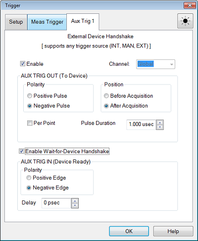
These signals can be used when the analyzer is communicating with a slow mechanical device. A material handler is very mechanical and takes a relatively long time to load and discharge parts. Here is how these signals work together to communicate:

  1. The analyzer sends a 'Ready' signal when it is ready to make a measurement.

  2. The external device sends a trigger signal to the analyzer  when it is ready for a measurement.

  3. Additional signals are available on the Handler I/O to indicate that the measurement sweep has ended, and that the handler can setup for the next measurement.


See how to access the Trigger Dialog

Dialog Settings

To cause the SSA to respond to Meas Trig IN or Handler I/O signals, select External on the Trigger Setup tab, Source setting.

Note: You must select External when you use any external triggers.

Also on the Trigger Setup tab, Scope setting, choose whether one external trigger signal will apply to ALL channels (Global) or one trigger signal per Channel. The following settings apply accordingly.
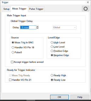
Main Trigger Input

Global / Channel Trigger Delay  After an external trigger is received, the start of the sweep is held off for this specified amount of time plus any inherent latency.

  • When Trigger Scope = Channel, the delay value is applied to the specified channel.

  • When Trigger Scope = Global, the same delay value is applied to ALL channels.

Source  The analyzer accepts Trigger IN signals through the following connectors:

  • Meas Trig IN BNC on the rear panel

  • Handler I/O

  • Pulse3: Trigger signals are routed internally without the need of a cable connection between the pulse 3 output and the external trigger input.

Level / Edge  

High Level  The analyzer is triggered when it is armed (ready for trigger) and the TTL signal at the select input is HIGH.

Low Level  The analyzer is triggered when it is armed (ready for trigger) and the TTL signal at the select input is LOW.

Positive Edge  After the analyzer arms, it will trigger on the next positive edge. If Accept Trigger Before Armed is set, the analyzer will trigger as soon as it arms if a positive edge was received since the last data was taken.

Negative Edge  After the analyzer arms, it will trigger on the next negative edge. If Accept Trigger Before Armed is set, the analyzer will trigger as soon as it arms if a negative edge was received since the last data was taken.

Accept Trigger Before Armed  When checked, as the analyzer becomes armed (ready to be triggered), the analyzer will immediately trigger if any triggers were received since the last taking of data. The analyzer remembers only one trigger signal. All others are ignored.

  • When this checkbox is cleared, any trigger signal received before analyzer is armed is ignored.

  • This feature is only available when positive or negative EDGE triggering is selected.

  • Configure this setting remotely using CONTrol:SIGNal (SCPI) .

Ready for Trigger Indicator (Trigger Ready)

On the analyzer, when External is selected on the Trigger Setup tab, then both Meas Trig IN and Meas Trig Ready are enabled.

Note: The Ready for trigger is available only when the trigger source is set at External.

Choose a connector to send the analyzer Ready OUT signal:

Choose Polarity of the 'Ready OUT' signal.

  • Ready High - TTL High indicates the analyzer is ready for trigger.

  • Ready Low - TTL Low indicates the analyzer is ready for trigger (default setting).

See Also


Aux Trig 1 dialog box help

See how to access the Trigger Dialog

AUX TRIG OUT and AUX TRIG IN

Note: AUX Trigger IN and OUT are supported only in Network Analyzer (Standard) and Spectrum Analyzer measurement classes. The other measurement classes do not support them.

These signals are highly configurable. They can be used with all types of external devices to send and receive signals. However, it is important to note that either Aux Trig INPUT does NOT trigger the VNA. That signal must be selected. See step 2 in the following procedure.

  1. An external source sends a 'Ready' signal to the VNA (at the Aux Trig IN connector) when it is settled at a frequency.

  2. After receiving the Ready signal, the VNA begins the measurement when it receives a Trigger signal from the specified Trigger Source:

    • Internal - Measurement begins immediately.

    • Manual - Measurement begins when the VNA Trigger button is pressed.

    • External - Measurement begins when Meas Trig In signal is received from an external device. This must be configured independently.

  • The Aux Trig OUT signal can be configured to be sent either just BEFORE the measurement is made or AFTER the measurement is complete. When communicating ONLY with an external source, the Aux Trig OUT signal should be sent AFTER the measurement is complete to indicate that the external source can setup for the next measurement.

Dialog Settings

The Aux Trig 1 tabs are identical. Two pair of connectors are available to allow two external devices to be controlled simultaneously.

Enable  Check to use the Aux connectors to output signals to an external device.

Channel:  This setting is controlled by a  Preference setting.

  • Global - ALL Aux Trig settings apply to ALL channels. The Per Point setting (see below) is made on the Trigger Setup tab which also applies to ALL channels.

  • Channel - ALL Aux Trig settings apply to the specified channel. Each channel can be configured independently.

AUX TRIG OUT (To Device)

The following settings control the properties of the signals sent out to the AUX connector.

Polarity

Positive Pulse  Outgoing pulse is positive.

Negative Pulse  Outgoing pulse is negative.

Position

Before Acquisition  Pulse is sent immediately before data acquisition begins.

After Acquisition  Pulse is sent immediately after data acquisition is complete.

Per Point  Check to cause a trigger output to be sent for each data point.  Clear to send a trigger output for each sweep.

When the Aux Trig - "Global" Preference is selected, then the Point setting is made on the Trigger Setup tab. It then applies to ALL channels. When more than one channel is present, the channel setting that was made last is used.

Pulse Duration  Specifies the duration of the positive or negative output trigger pulse.

Enable Wait-for-Device Handshake

When checked, the analyzer waits indefinitely for the input line at  the application IO (pin 7)   to change to the specified level before acquiring data. This signal indicates that the external device is ready for analyzer data acquisition. If the signal arrives before the analyzer  is ready to acquire data, it is latched (remembered).

When NOT checked, the analyzer does not wait, but outputs trigger signals when the SSA is ready.

This signal does NOT trigger the analyzer. The trigger signal is generated from Trigger Sources: Internal, Manual, or External.

IN (READY)

Positive Edge  The analyzer responds to the leading edge of a pulse on the Aux1 or Aux2 In connector.

Negative Edge  The analyzer  responds to the trailing edge of a pulse on the Aux1 or Aux2 In connector.

Delay  Time that the analyzer waits after receiving the Handshake input before data acquisition begins.

See Also

  • See how to use these connectors to synchronize with External Sources.

  • Pulse Triggering