When a power meter is configured as a VNA receiver (in standard measurement channels ONLY), you can
Extend the number of measurement receivers
Use the power meter as a scalar detector
Monitor the power at any point in a measurement system
Use multiple power meters in a Guided Power Cal to cover a wide frequency range
Use the power meter to level the stimulus power at any point in a measurement system
Use the power sensor as a PMAR device to confirm the accuracy of a Source Power Cal Learn how
Once configured, a power meter can be used like any other VNA receiver in the following dialogs:
New Trace/Meas dialog - used in Ratioed and Unratioed measurements.

Frequency Offset Mode - Extend frequencies beyond VNA
Important first-time USB connection note
How to Create and Configure a PMAR DeviceVNA Applications have additional methods of launching this dialog. |
|
Using Hardkey/SoftTab/Softkey |
|

|
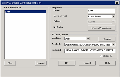
This dialog allows you to create and configure a power meter to be used as a receiver by the VNA. Once you create and configure a power meter from this dialog box, it becomes available from VNA dialog boxes as well as the softkeys and entry toolbar, as if it were an internal VNA receiver.
External Devices The devices that are currently configured appear in this list. The number of devices that can be configured is limited by the specified Interface. New - Click to create a new PMAR configuration. The default name is Device<n>, where <n> is the next number for 'Device'. Remove - Click to remove the selected device from the list.
Properties Name - Enter a device name as it will appear when referring to this device in all VNA dialog boxes. Edit the name at any time. Duplicate names are not allowed.
Device Type - Select Power Meter. Driver - Use AGPM for all Keysight Power Meters. See Supported Power Meters Active - Check to make the device available for use in the FOM, New Trace, and Receiver Leveling dialogs. An instrument state that is saved with an Active device (checked) will include the device in the state file. Otherwise, if the Active box is cleared, the device will NOT appear in the state file. Note: Multiple PMAR configurations for the same physical device can be Active and Enabled. Device Properties - Click to launch the Configure Power Sensor dialog.
IO Configuration Interface Select the interface that is used to connect the device to the VNA. These devices will then appear in the 'Available' field. Choose from:
Available - Shows a list of devices that are connected to the specified IO Interface. Refresh - Click to rescan the specified interface for devices. Selected - Enter the IO configuration or select from the available list of IO Interfaces found. Enable I/O - Clear this box to disable communication with the selected device. You would do this to configure a device that is not yet connected to the VNA.
Configure Alias and LAN Devices Use this procedure to configure a device using a LAN interface. Also use for ANY device for which you want to set an alias (easily-recognized) name. The alias name appears in the Available field when Aliases is selected as the Interface.
To Add a LAN Device:
To create an Alias for a connected device:
|

|
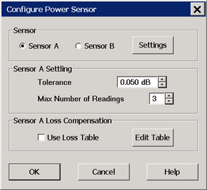
To launch this dialog, with the PMAR device selected in the External Device Configuration dialog, click Device Properties . This dialog is used to configure a power meter / sensor for use as a receiver. To configure a single power meter for a Source Power Cal, use the Power Meter Settings dialog.
Note: By default, a PMAR is de-activated when the VNA is Preset or when a Instrument State is recalled. This behavior can be changed with a Preference setting.
Sensor For power sensors that are connected to a power meter, select a sensor to configure. Settings - Click to launch the Power Sensor Settings dialog. When pressed, communication with the sensor is tested. Sensor settings can NOT occur unless Enable I/O is checked on the External Device Configuration dialog, and the sensor is properly connected and configured.
Sensor Settling Each power meter reading is "settled" when either:
The readings that were taken are averaged together to become the "settled" reading. Tolerance - When consecutive power meter readings are within this value of each other, then the reading is considered settled. Max Number of Readings - Sets the maximum number of readings the power meter will take to achieve settling.
Sensor 'N' Loss Compensation Use Loss Table - Select this checkbox to apply loss data to Source Power calibration correction (such as for an adapter on the power sensor). Edit Table - Invokes the Power Loss Compensation dialog box.
|

|
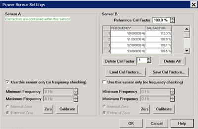
This dialog appears when you click the Settings button on the Configure Power Sensor dialog. Note: Be sure that the frequency range of your power sensor covers the frequency range of your measurement. This does NOT occur automatically. Sensor A (B) - Displays one of the following messages depending on type of sensor.
Load Cal Factors - Click to load cal factors from a *.csv file that you create from the cal factors that appear on the sensor. The first line of the file MUST have the reference Cal Factor (typically 100), followed by Freq/Cal Factor pairs as show in the following image:
Save Cal Factors - Click to save the cal factor table to a *csv file. Limit Frequency Range
Minimum Frequency - Specifies the minimum frequency range for the sensor. Maximum Frequency - Specifies the maximum frequency range for the sensor.
Zero and Calibrate the Power Sensor For highest accuracy, Zero AND Calibrate the power sensor before measuring data. Follow prompts that may appear. Zero - If the following settings are 'greyed', Internal or External zeroing is selected automatically based on the power meter/sensor model. Otherwise, select the appropriate type of zeroing to perform, then press Zero.
Calibrate - Available when the selected sensor has calibration capability. Calibration involves measuring an internal 1 mW source.
Press Calibrate, then follow the prompts. |

|
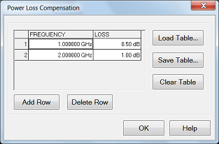
Add Row - Add a row at the end of row. Delete Row - Delete the selected row. To Edit a value, double-click in the cell to be edited. Compensates for losses that occur when using an adapter or coupler to connect the power sensor to the measurement port. These components will be removed when the calibration is complete. To account for components that will remain during the measurement, use the Power Offset setting. The Frequency/Loss pairs define the amount of loss for the entire frequency range. For example, using the entries in the above dialog image:
Frequency - Enter a frequency in Hz. Loss - Enter a loss as a POSITIVE value in dB. To compensate for gain, use NEGATIVE values. Load Table... - These values can be loaded from an S2P file using the Characterize Adapter/Fixture. Note: Large segment counts with one or more power sensors can result in long load and close times for the VNA Application. Save Table... - Save the table into csv file. Clear Table - Clears all rows and data. The Power Loss Compensation table survives VNA Preset and Power OFF. To NOT use Loss compensation, clear the Use Loss table checkbox on the Configure Power Sensor dialog. |
Learn how to create and configure PMAR device.
After a Source Power Cal has been performed, use the same sensor as a configured PMAR to analyze the accuracy of the Calibration.
Create a PMAR device with the power sensor that will be used for the Source Power Cal.
Perform a Source Power Cal. Learn how.
Create an unratioed measurement with the PMAR device. Learn how.
With the power sensor still connected to the test port, monitor the corrected source power using Min and Max markers or the Trace Statistics peak-to-peak feature.
Last Modified:
|
18-May-2016 |
First Release |