|

Learn about Receiver Leveling (scroll up).
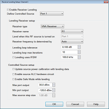
Define Controlled Source (Port)
Each source port to be leveled is configured individually. Select a source to be configured for receiver leveling. Choose from: port number, or any active external RF source. Learn more about External Devices.
Leveling Receiver Setup
Receiver Type Receiver type does an initial sort to make it easier to select a receiver. Choose from: VNA Receiver or Ext. Device (PMAR).
Receiver Select a receiver to be used to level the specified source.
For VNA Receiver type, choose from any VNA receiver using standard or receiver notation.
To level power at the source output or DUT input choose the reference receiver for the source port. For example, to level the source power at port 1, then choose "R1". To level power at the DUT output, choose the receiver that is used to measure the DUT output. If the DUT output is connected to port 2, then select "B" or 'b2". Learn about Receiver Notation.
For Ext Device type, choose a configured PMAR device.
Level when this RF source is turned ON: The Controlled Source is selected automatically and can NOT be changed.
Receiver frequency is determined by: Available ONLY when the selected receiver is a VNA Receiver or power meter. This setting determines which receiver frequencies are measured. Choose from:
-
Auto - always uses the frequency range that is assigned to the measurement receiver.
-
FOM Receiver - FOM Receiver frequency range. Learn more about Frequency Offset Mode.
-
FOM Source - FOM Source frequency range.
-
DUT Input - Mixer/Converter input frequency range.
-
DUT Output - Mixer/Converter output frequency range.
Leveling Loop Tolerance The source is considered leveled when each stimulus data point has achieved the power level +/- (plus or minus) this tolerance value.
Leveling Loop Max Iterations If every stimulus data point does NOT achieve the port power after this number of leveling sweeps, the measurement sweep occurs using the correction values obtained from the last leveling sweep. The message: Not settled, noisy trace appears when the Max Iterations is reached. If you see this message, you can increase the Max Iterations, reduce the IFBW, or increase the Tolerance setting.
Leveling IFBW Available only for VNA receivers. By default, the IFBW for the leveling sweeps is set to 100 kHz. Learn more about IFBW.
-
Increase this value to make faster, but noisier leveling sweeps.
-
Decrease this value to maker slower, more repeatable leveling sweeps.
-
Uncheck the box to use the same IFBW as the measurement sweeps.
Controlled Source Setup
Update source power calibration with leveling data Available only when using an RF Source and VNA receiver.
-
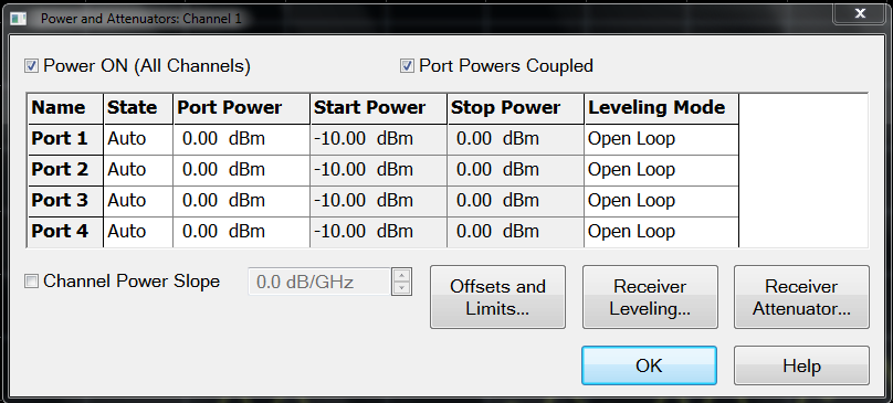
When checked, the latest correction data is copied to the Source Power Cal correction array. When Leveling Mode is switched back to Internal (on the Power and Attenuators dialog), Source Power Cal is automatically turned ON using this correction data.
-
When cleared, Source Power Cal is NOT turned ON when Leveling Mode is switched back to Internal.
Enable Source ALC hardware circuit Available only when a VNA source is selected.
-
When checked, VNA internal leveling hardware is used. (Recommended)
-
When cleared, Open Loop hardware is used.
Enable Safe Mode while leveling
To protect your DUT, these settings control the extent to which the source power will be changed to achieve the port power as measured at the reference receiver. These settings could be necessary when using external components with a large variation in frequency response (flatness).
When checked:
When cleared:
-
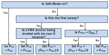
The initial power for the leveling loop may be determined by the Min source output, the Max source output, the last setting of the leveling loop, or the target value of the leveling loop. See Initial Power below.
-
The Max source step size is ignored.
Max source step size When Safe Mode is enabled, the change in source power at each data point from one sweep to the next is limited to this value. For example, assume Safe Mode is enabled, and Max Power Step is set to 1 dB. On the first leveling sweep, the first data point measures 3 dB lower than the port power, then source power for data point 1 will be increased by 1 dB for the next sweep, and likely for the following two sweeps.
Max port output Always limits the maximum power out of the source to this value. The message: Power set to Max Power appears when this limit is reached.
If the maximum port power out of the VNA is reached at any time during the leveling sweeps, the following message appears: Power set to user power limit.
Min port output Always limits the minimum power out of the source to this value. The message: Power set to Min Power appears when this limit is reached. When Safe Mode is enabled, this value is used as the initial power level for the leveling loop process
|


