Mobile WiMAX STC/MIMO/SISO Configuration

The Signal Studio for Mobile WiMAX advanced carrier mode supports testing of the STC/MIMO features needed for Wave 2 of the WiMAX Forum’s Radio Conformance Test, including:

STC/MIMO/SISO Parameters Setting for DL-PUSC

Supported STC/MIMO/SISO Mode for

DL-PUSC

Parameter Settings

Number of BS Antennas

Number of MS Antennas

Function Selection

(In System Configuration Wizard)

Instrument Setup

Channel State

STC Type

Waveform Output Mode

Simulate Transmitter Antenna Signals

STC (Matrix A)

2-antenna  

2

-

Multiple Antennae

Two Instruments

Off

Matrix A

Downlink Only (TDD) or

Downlink Only (FDD)

MIMO (Matrix B)

2-antenna

2

2

Multiple Antennae

Two Instruments

Off

Matrix B

Downlink Only (TDD) or

Downlink Only (FDD)

SISO

1

1

Single Antenna

One Instruments

Off

None

Downlink Only (TDD) or

Downlink Only (FDD)

Simulate Receiver Antenna Signals

STC (Matrix A), one-antenna  
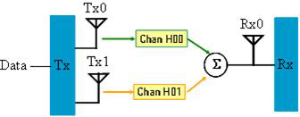
2

1

Single Antenna

One Instruments

On

Matrix A

Downlink Only (TDD) or

Downlink Only (FDD)

STC (Matrix A), 2-antenna
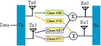
2

2

Multiple Antennae

Two Instruments

On

Matrix A

Downlink Only (TDD) or

Downlink Only (FDD)

MIMO (Matrix B), 2-antenna

2

2

Multiple Antennae

Two Instruments

On

Matrix B

Downlink Only (TDD) or

Downlink Only (FDD)

SISO

1

1

Single Antenna

One Instruments

On

None

Downlink Only (TDD) or

Downlink Only (FDD)
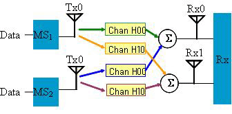
Collaborative SM/SISO Parameters Setting for Uplink

Supported Collaborative SM/SISO Mode for Uplink

Parameter Settings

MS Antenna Number

BS Antenna Number

Function Selection

(In System Configuration Wizard)

Instrument Setup

Channel State

Collaborative Burst

Waveform Output Mode

Simulate Transmitter Antenna Signals

Collaborative SM 1x2 to simulate the antenna on one of the MS

1

2

Single Antenna

One Instruments

Off

Added in PUSC Zone

Uplink Only (TDD) or

Uplink Only (FDD)

Collaborative SM 1x2 to simulate both antennas of the two MS1

1

2

Multiple Antennae

Two Instruments

Off

Added in PUSC Zone

Uplink Only (TDD) or

Uplink Only (FDD)

SISO

1

1

Single Antenna

One Instruments

Off

None

Uplink Only (TDD) or

Uplink Only (FDD)

Simulate Receiver Antenna Signals

UL Collaborative 1x2 SM2

1

2

Multiple Antennae

Two Instruments

On

Added in PUSC Zone

Uplink Only (TDD) or

Uplink Only (FDD)

SISO

1

1

Single Antenna

One Instruments

On

None

Uplink Only (TDD) or

Uplink Only (FDD)

1. When fading is not turned on, this software creates waveforms that correspond to the transmitted signals from the two subscriber stations. The master instrument will have the signal from the first subscriber with pilot pattern A, while the slave source will have the signal from the second subscriber with pilot pattern B. In this case, you can not combine regular data bursts with the collaborative SM burst, because those would be coming from other subscribers.

2. When fading is enabled, this software generates the waveforms that would be received by the two base station antennae. In this scenario, you can include both regular bursts and the collaborative bursts. Two sets of fading channel parameters can be specified, each representing the conditions between one of the subscriber stations and the two base station antenna in a 1x2 SM configuration. The first set of channel parameters are applied to any regular bursts.