2. Basic: Baseband Channel Assignment (PXB)
Range: for specified range values, see the signal generator's data sheet
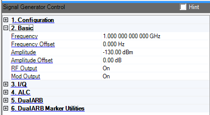
Set or change the signal generator's carrier frequency. The default values are specific to the system configuration:
MXG Internal Arb: 1.0 GHz
ESG/PSG Internal Arb: 1.0 GHz
PSG Option 015/016: 10 GHz
The signal generator output frequency is:
Signal Generator Output Frequency = Frequency – Frequency Offset
Minimum Frequency = 100 kHz + Frequency Offset
Maximum Frequency = SigGen Max + Frequency Offset
Range: –200 to 200 GHz
Set or change the frequency range limits and the visual display on the signal generator. It allows the source frequency display to account for a system with frequency translation in it.
The actual output frequency and frequency range limits for the signal generator are offset by the frequency offset value.
Signal Generator Output Frequency = Frequency – Frequency Offset
Minimum Frequency = 100 kHz + Frequency Offset
Maximum Frequency = Signal Generator Max + Frequency Offset
Range:
MXG: –144 to 17 dBm
ESG: –136 to 30 dBm
PSG: –130 to 30 dBm
Set or change the signal generator output amplitude.
The actual output amplitude and amplitude range limits are offset by the amplitude offset:
Signal Generator Output Amplitude = Amplitude – Amplitude Offset
Minimum Amplitude = Signal Generator Minimum + Amplitude Offset
Maximum Amplitude = Signal Generator Maximum + Amplitude Offset
It is not possible to set the maximum amplitude level with the ALC set to On.
PSG Maximum = 30 dBm, Maximum with ALC Enable = On, 25 dBm
ESG Maximum = 25 dBm, Maximum with ALC Enable = On, 20 dBm
When Attenuator Hold is Off, setting the amplitude also sets the ALC level and the attenuator. The ALC level and attenuator value are chosen to keep the ALC level at its optimum level.
When the Attenuator Hold is On, the attenuator value is held constant. Changing the amplitude or ALC level causes the other parameter to change an equal amount. In general, ignoring amplitude offset, the output amplitude is:
Amplitude(dBm) = ALC Level(dBm) – Attenuator Value(dB)
Range: –200 to 200 dB
Set or change an offset to the value and range limits of the signal generator amplitude.
If there is an amplifier with 10 dB of gain on the output of the signal generator, the amplitude offset should be set to 10 dB. Now all entries to the amplitude value account for this external gain.
The actual output amplitude of the signal generator is:
Signal Generator Output Amplitude = Amplitude – Amplitude Offset
Range: 1 to 16
Default: 1
When you establish a connection between the Signal Studio software and the PXB, Signal Studio recognizes the number of baseband generators (BBGs) in the currently loaded PXB configuration. Signal Studio creates a waveform file (Ant0, Ant1, Ant2, and so on) for each antenna configured in the System Configuration Wizard. The default behavior is for Signal Studio to download waveform file Ant0 to BBG1 in the PXB, waveform file Ant1 to BBG2, and so on. In the Baseband Channel Assignment cell, the default BBG assignments are displayed as a comma-separated list (1,2).
The Baseband Channel Assignment parameter enables you control the assignment of each waveform file to a specific BBG resource, rather than accepting the default. You can assign Ant0 to BBG2 and Ant1 to BBG1 by making the corresponding change to the comma separated list (2,1).
Double-click or use the drop-down menu to control the operating state of the RF signal.
Double-click or use the drop-down menu to turn the signal generator RF modulation on or off. This function turns on or off all enabled modulation formats including I/Q modulation, pulse modulation, AM, FM, and so on.
2. Basic