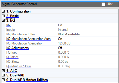
I/Q instrument settings are not available for the E6607 EXT.
Double-click or use the drop-down menu to turn the IQ modulation on or off.
Displays the source of the IQ inputs. This information is taken from the hardware configuration and is a read-only feature.
Choice: 40 MHz | Through
Double-click or use the drop-down menu to select a 40 MHz lowpass filter or a Through path.
The 40 MHz filter helps reduce broadband noise and spurs for signals with an 80 MHz or less RF bandwidth. This parameter should be set to when using signals that have RF bandwidths greater than 80 MHz. The filter has no affect on the MXG and PSG Option 015/016 wide band signal path.
Set to to enable this feature.
Choice: On | Off
Default: On
Double-click or use the drop-down menu to turn I/Q modulation attenuation auto on or off.
The signal generator will automatically set the IQ modulation attenuator value to optimize signal performance at the RF output when Modulation Attenuation Auto is set to On. When ALC Enable is On, the RF output Amplitude will not change while the attenuator value is changed until the ALC range is exceeded.
Range: 0 to 40 dB
Set or change the I/Q modulation attenuation to optimize signal performance at the RF output. The modulator attenuator is an electronic attenuator in the IQ path before the IQ modulator. When ALC is On, the RF output amplitude will not change while the attenuator value is changed until the ALC range is exceeded.
Set to to enable this feature.
The default Modulation Attenuation value is system configuration specific:
MXG Internal Arb: 12 dB
ESG/PSG Internal Arb: 12 dB
PSG Option 015/016: Disabled
Double-click or use the drop-down menu to enable or disable adjustments to the I/Q modulation input.
Range:
MXG: –20% to 20%
ESG/PSG: –50% to 50%
Set or change a DC offset to the I signal before the IQ modulator. It can be used to help minimize carrier leakage or to introduce calibrated impairments.
Set to to enable this parameter.
Range:
MXG: –20% to 20%
ESG/PSG: –50% to 50%
Set or change a DC offset to the Q signal before the IQ modulator. It can be used to help minimize carrier leakage or to introduce calibrated impairments.
Set to to enable this parameter.
Range:
MXG: –800 to 800 nanoseconds
ESG/PSG: –2.0 to 2.0 seconds
Set or change the time delay between the I and Q paths. A positive value delays the I signal relative to the Q signal, and a negative value delays the Q signal relative to the I signal.
Set to to enable this parameter.
Range: –10.0 to 10.0 degrees
Set or change the phase angle between the I and Q vectors. When the quadrature skew is zero, the phase angle is 90 degrees. Positive skew increase the angle from 90 degrees while negative skew decreases the angle from 90 degrees.
Set to to enable this parameter.
3. I/Q