4. ALC: ALC Trigger Source bus (M9381A)
4. ALC: ALC Mode (M9381A)
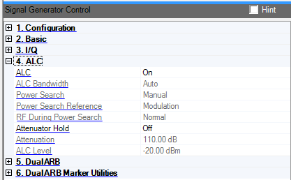
The RF output power of the signal generator is constantly monitored and controlled by the automatic leveling control (ALC) circuit. Its purpose is to hold output power at its desired level in spite of drift due to temperature and time.
There are some modulation conditions the ALC circuit cannot handle properly that lead to output level errors. In these conditions, better power level accuracy can be obtained by turning the ALC off and using power search. ALC off is useful with pulse modulation when the pulse width is narrower than two microseconds.
Pulse modulation is accomplished using a modulator which precedes the ALC detector. The ALC must, therefore, measure a pulsed signal, and it is able to do this if the pulse width exceeds two microseconds. For narrower pulses, set the ALC to off.
Double-click or use the drop-down menu to turn the automatic level control on or off. It is not possible to set the ESG/PSG maximum amplitude level with ALC On.
PSG Max = 30 dBm, Max with ALC on, 25 dBm
ESG Max = 25 dBm, Max with ALC on, 20 dBm
MXG Max = 17 dBm, Max with ALC on, 17 dBm
Choices: Auto, 100 Hz, 1 kHz, 10 kHz, 100 kHz
Double-click or use the drop-down menu to select the ALC loop bandwidth. The Auto selection lets the signal generator select the bandwidth automatically based on the current signal setup.
ALC Bandwidth is not available for MXG.
100 kHz is not available with the ESG.
Double-click or use the drop-down menu to select either manual or auto as the power search mode. When is set to , power search will not run until the Power Search button is pressed. When is set to , power search will run automatically with each change to the RF frequency or power, and with each change to the AM, burst, pulse, or I/Q modulation state.
Set to to enable this feature. More information...
This parameter is not available for MXG.
Choice: Modulation | Fixed
Default: Modulation
Double-click or use the drop-down menu to select a fixed or modulation reference signal when doing a power search.
Fixed − power search uses a fixed 0.5 V reference.
Modulation − power search uses the RMS value of the current I/Q modulation as the reference.
Set to to enable this parameter.
This parameter is not available for all instrument models and may be greyed out or not shown in GUI.
Choice: Normal | Minimum
Default: Normal
Double-click or use the drop-down menu to select the level of the output power control during a power search routine.
Normal − performs power searches without setting the internal step attenuator to its maximum setting. Glitches and power changes may be present during the search.
Minimum − sets the signal generator's step attenuator to its maximum setting during power search to protect sensitive circuits.
Set to to enable this parameter.
Choice: On | Off
Default: Off
Double-click or use the drop-down menu to enable or disable the signal generator’s attenuator hold function.
On − locks the attenuator at its current setting to prevent glitches. Use this function to prevent power discontinuity normally associated with the attenuator switching during power adjustments.
Off − leaves the attenuator in a dynamic state. Setting the amplitude also sets the ALC level and the attenuator.
You can use this function any time you want to guarantee that there will be no power discontinuity normally associated with the attenuator switching during power adjustments.
Range:
MXG: 0 to 130 dB; Default: 110 dB
ESG: 0 to 130 dB; Default: 125 dB
PSG: 0 to 115 dB; Default: 115 dB
Set or change the value of the output attenuator. Changing the amplitude or ALC level causes the other parameter to change an equal amount. The ALC level and attenuator value are chosen to keep the ALC at its most effective level.
Set to to enable this feature and hold the attenuator value constant.
Range:
MXG: –32 to 17 dBm; Default –20 dBm
PSG: –15 to 25 dBm; Default –15 dBm
ESG with Option UNB: –13 to 25 dBm; Default –15 dBm
ESG with Electric Atten: –13 to 20 dBm; Default –15 dBm
Set or change the output power level using only the ALC. When the ALC circuit is on, the output power level is constantly monitored and controlled. When the ALC circuit is off, the output power level is not controlled.
Set to to enable this feature.
Choice: AUTO | PXI0 | .. | PXI7
Default: None
Double-click or use the drop-down menu to select a bus for ALC hold signal path on PXI backplane. This parameter is only available when connected to the M9381A.
Choice: : Off | HOLD | TRACK
Default: Off
Double-click or use the drop-down menu to select ALC mode. This parameter is only available when connected to the M9381A.
4. ALC