S-Parameter Calibration
Note: Perform this
calibration before the Source
Modulation Calibration.
See also
The example procedure in this topic describes how to perform a typical
calibration using the Cal All Calibration Wizard method, which allows
multiple channel calibrations in a single session. For more information
about this calibration method, refer to Calibrate
All Channels.
Ensure that the Modulation Distortion measurement
class to be calibrated is currently active.
Press Cal >
Main > Cal
All... to launch the following dialog showing the active measurement
class:
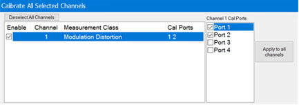
Select the ports.
Click Next,
then confirm or change the calibration properties in the Measurement
Class Cal Properties dialog:
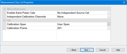
Click Next.
to access the Calibration Attenuator
Settings dialog:
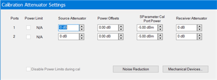
In
the Calibration Attenuator Settings
dialog, perform the following:
Set the attenuator settings. Learn
more.
Click on the Noise
Reduction button to improve measurement accuracy. Learn more.
Click on the Mechanical
Devices button to view all switches and attenuators
in the VNA. Learn
more.
Click Next,
then select the DUT connectors and calibration kits in the Select
DUT Connectors and Cal Kits dialog.
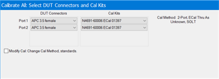
Click Next
to access the Power Cal Settings
dialog.
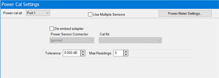
In the Power Cal
Settings dialog, set the desired Tolerance and Max Readings.
Learn more about Accuracy
Tolerance and Max
Number of Readings.
Click Next
and follow the calibration process until completed.
Calibration
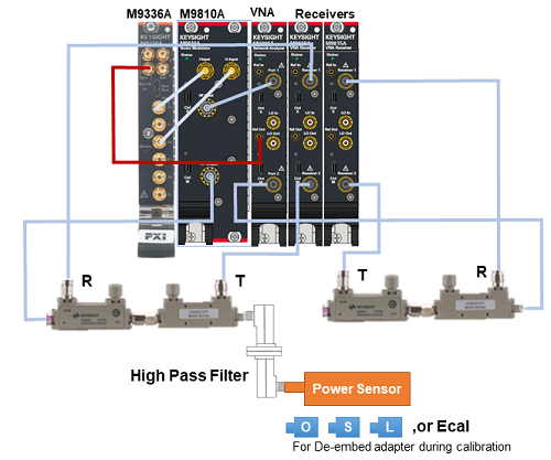
for the configuration with M981xAS option 750 (M9810A and M9336A)
A high pass filter is required between
the coupler's output port and a power sensor during power calibration
process during the calibration in order to get better power measurement
accuracy. The "De-embedded adapter" check box should be checked
and the appropriate power sensor connector and cal kit should be selected
at step 8 in the procedure above.
Note:
When you have the filter
between M9810A RF output and coupler input, it is not necessary to put
the filter between the coupler's output port and a power sensor. "De-embedded
adapter" is not necessary in this case.
Measurement
Frequency Range |
Recommended
Filters |
20 G to 26.5 GHz |
Keysight
K281C Coaxial Waveguide Adapter, 2 ea. or equivalent filter (Eravant
SCF-15312340-42KFKF-H1, 1ea.) |
26.5 G to 40 GHz |
Keysight
R281A Coaxial Waveguide Adapter, 2 ea. or equivalent filter (Eravant
SCF-22318340-28KFKF-H1, 1ea.) |
33 G to 44 GHz |
Keysight
Q281A Coaxial Waveguide Adapter, 2 ea. or equivalent filter (Eravant
SCF-27324340-222F2F-H1, 1 ea.) |
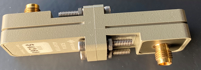
Waveguide Filter (High Pass Filter)
Two coaxial waveguide adapters can
be a high pass filter.
Example: two Keysight R281As (26.5G
to 40GHz)
