-
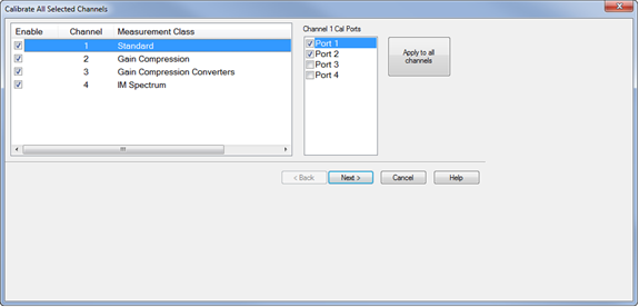
Check the channels to be calibrated.
-
Check the ports to be calibrated. Click on the Apply to all channels button to apply the port selections to all channels.
-
Click Next>
"Cal All" allows you to calibrate multiple channels in a single calibration session. This not only reduces the number of connections that need to be made, but also the number of cal standard measurements that must be performed.
In this topic:
Cal All Channels Calibration (links to SCPI Cal All Channels programming examples)
Cal All offers a single, optimized calibration procedure for all channels (with some limitations, see below). The optimizations include:
Minimizing the number of physical connection of standards.
Minimizing the number of power meter calibration sweeps.
User-settable power levels for S-Parameter as well as power calibration steps.
Accounting for different switch and attenuator settings among different channels. This reduces the number of measurements required to characterize different switch/attenuator settings (channel setup differences).
Cal All will produce the same number and format of Cal Sets (error terms) that would be realized had the calibrations been performed one at a time.
Calibrate External Sources that are connected to the analyzer using Configure an External Source.
Beginning with the A.18.40 release, Cal All supports the following internal setting difference. Call All takes all required calibration data for each setting below during the Call All sequence.
Factory Cal On/Off
A port of Split Port Calibrations
M983xA
Gain Coupling On/Off
Path Configuration (Except following elements)
IFAntiAliasFilter
PulseModDrive
PulseModPort<SP#>
PulseTrigInput
SMC+ Phase with phase enabled is supported using a known delay mixer or a phase reference cal set. S2P file characterized mixers are NOT supported.
Cal All is performed at one IFBW.
All channels that are calibrated are forced into stepped sweep mode.
All channels to be calibrated MUST have the same cal reference plane. In other words, Cal All cannot compensate for any path changes that occur external to the analyzer.
Cal All cannot be used for the following configurations with Swept IMD and IM Spectrum (for these configurations use the Cal Wizard instead):
Port 3 as input and port 4 as output using an external combiner.
Using an N5242B with external combiner that has a large path loss difference from the internal combiner.
When calibrating systems with a mix of internal and external couplers, the Cal All attenuator settings must be set to match the client channels, otherwise the Source Power Calibration may be incorrect.
Calibration All channels for Noise Figure measurement channels is not supported on M980xA.
How to perform a Cal All Channels Calibration |
|
Using Hardkey/SoftTab/Softkey |
|
|
|
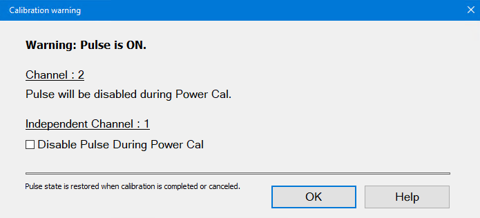
A warning dialog will be displayed if any of the ports being calibrated have pulse modulators enabled. Typically, cal all will perform all calibration steps with background channels and will never enable pulse during the calibration steps. In this case, the warning is just informative. There is nothing that needs to be changed.
However, cal all allows some channels to be calibrated as “Independent Channels”. (These app types can be set as independent channels in cal all: STD, SMC, GCA, GCX, NF, NFX, IMD, IMDX). Independent channels are calibrated using the exact stimulus of the active channel. For channels declared as “Independent”, the user may choose to turn off pulse during the power cal. When finished, all user channels will retain their original settings.
Confirm or change the following unique cal properties for each channel to be calibrated. Click a link to learn about these properties. The properties with (NOT available in Cal All) are NOT available in a Cal All calibration as they are in a stand-alone calibration. Differential IQ
Spectrum Analyzer
Gain Compression
GCX (Gain Compression Converters)
Noise Figure and NFXNote: Calibrate All Channels for Noise Figure measurement channels is not supported on M980xA, P50xxA/B and E5080B.
|
|||||||||||||||||||||||||||||||||||||||||||||||||||||||||||||||||||||||||||||||||||||||||||||||||||||||||||||||
|
|
Programming |
|
|
UI Setting |
Property |
Value |
|
"Max Product Order" |
Integer indicating desired product order. |
|
|
"Include 2nd Order" |
"true" or "false" |
|
|
"Exclude Channels From 2nd Order" |
|
|
|
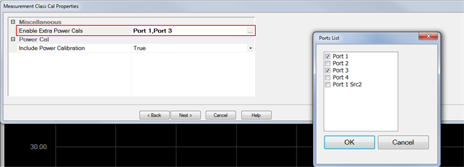
Enable Extra Power Cals |
"Enable Extra Power Cals" |
"Port 1", "Port 2", "Port 3", "Port 4", "Port 1 Src2", and/or Source3 |
|
"Independent Calibration Channels" |
Any selected channels that support SmartCal. |
|
|
Split Port Calibration Channels |
Any selected channels that support Split Port Cal. |
|
|
Response only |
|
|
|
Center Frequencies only |
|
|
|
|
Programming |
|
|
UI Setting |
Property |
Value |
|
Enable Extra Power Cals |
"Enable Extra Power Cals" |
"Port 1", "Port 2", "Port 3", "Port 4", "Port 1 Src2", and/or Source3 |
|
"Independent Calibration Channels" |
Any selected channels that support SmartCal |
|
|
Calibration Span (MOD only) |
"Calibration Span" |
"User Span" or "Instrument Span" |
|
Calibration Points (MOD only) |
"Calibration Points" |
Integer indicating number of calibration points |
|
Enable Phase Correction (MODX only) |
"Enable Phase Correction" |
"true" or "false" |
|
Phase Correction Method (MODX only) |
"Phase Correction Method" |
"Use Mixer Delay" "Use Receiver Characterization Calset" |
|
Calset (MODX only) |
"Calset" |
String of Cal Set Name |
|
|
Programming |
|
|
UI Setting |
Property |
Value |
|
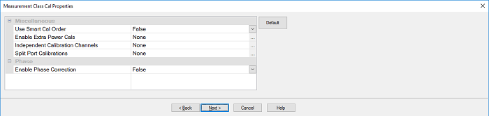
Use Smart Cal Order |
"Use Smart Cal Order" |
true or false Cal All optimizes the order of the calibration standards for acquisition to improve calibration results. This may result in a different order than a single channel Smart Calibration. Use “True” to have Cal All attempt to preserve the order of Smart Cal. depending on the client channels selected for calibration, this may not be possible due to incompatible order between channels. |
|
"Enable Phase Correction" |
"true" or "false" |
|
|
"Phase Correction Method" |
"Use Mixer Delay" "Use Characterized Mixer" "Use Receiver Characterization Calset" |
|
|
Mixer Delay |
"Mixer Delay" |
Real number indicating delay value. |
|
Receiver Characterization Cal Set |
"Calset" |
String of Cal Set Name |
|
Enable Extra Power Cals |
"Enable Extra Power Cals" |
"Port 1", "Port 2", "Port 3", "Port 4", "Port 1 Src2", and/or Source3 |
|
"Independent Calibration Channels" |
Any selected channels that support SmartCal. |
|
|
Split Port Calibration Channels |
Any selected channels that support Split Port Cal. |
|
|
Characterized mixer (s2p file) |
|
|
|
Phase Import Port |
"Phase Import Port" |
"Autoselect", "Port 1", "Port 2", etc. |
|
|
Programming |
|
|
UI Setting |
Property |
Value |
|
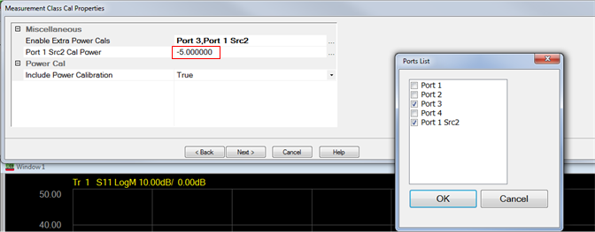
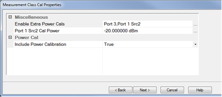
"Include Power Calibration" "Enable Extra Power Cals" "Port 1 Src2 Cal Power" |
"true" or "false" "Port 1", "Port 2", "Port 3", "Port 4", "Port 1 Src2", and/or Source3 Integer indicating valid calibration power. For example, "-20" indicates a power level of -20 dBm. Only valid if an independent port calibration on Port 1 Src2 is selected. |
|
|
"Independent Calibration Channels" |
Any selected channels that support SmartCal. |
|
The power cal is optional only if none of the selected channels require a power cal.
|
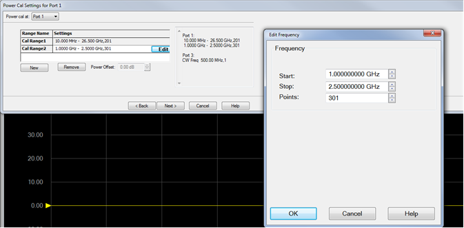
Independent Power Calibration Several applications control internal and external sources in a mode that is often decoupled from the span over which the receivers are swept. This includes, for instance, Differential IQ, and Spectrum Analyzer. Cal All can add a power calibration for any port (including external sources) over an arbitrary frequency span defined by the user. For all ports selected for an independent power calibration (except for Port 1 Src 2, see below), a power sensor calibration measurement is performed. The resulting source match correction terms are added to the calsets for ALL channels selected for the Cal All calibration. The power calibrations used in Cal All have all the same features as typical power calibrations. These include the ability to specify power offsets, the power at which the calibration is completed, and the ability to use multiple power sensors (note that using multiple power sensors is a feature only available on regular PNA ports – that is, not external sources or auxiliary ports). Port 1 Src2 Calibration The Port 1 Src2 calibration is a special case: In this case, a calibration is requested for situations where the Port 1 Bypass Switch is in “Combiner Path” mode and either the “Port 3 Bypass Switch” (4-port PNA-X) or the “Source 2 out 1 Bypass Switch” (2-port 2-source PNA-X) is also in “Combiner Path”. Therefore, if a user requests a calibration of this port:
Important Notes:
Independent Power Calibration for Cal All Setup
|
|
Beginning with firmware revision A.18.40, there are new attributes called Split Port Cal that allow channels to perform the calibrations without a thru calibration. When a thru calibration is difficult to take, it is possible to execute 1 port calibration only for each port. This is called as "Split Port" Cal. This feature is available in GCX, SMC, DIQ, and IMDX measurement classes only. DIQ and IMDX are available starting in A.19.10 Note: This feature replaces "Split Cal," which was available between A.13.67 and A.17.60. Note: Frequencies chosen for DIQ channels will be:
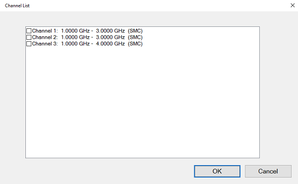
When you click ..., the channel which supports Split Port cal is displayed. Select the channel which you want to execute the calibration without thru.
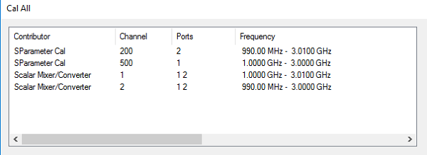
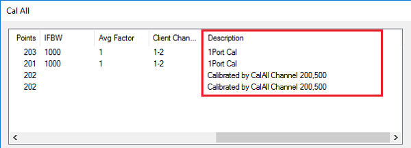
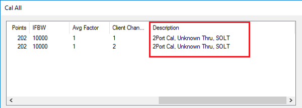
On the last Cal All Wizard page, the Description column specifies whether the channel is being calibrated by Cal All or performing its own calibration: If it is being calibrated by Cal All, it displays which Cal All channel is performing the calibration. |
|
Beginning with firmware revision A.13.67,there are new attributes called Independent Calibration Channels that allow channels to perform the calibrations as a independent calibration a SmartCal. This is an advanced feature. For example, it can make the calibration better by avoiding additional calculations associated with path difference betweem channels on the PNA. Any selected channels will perform their own SmartCal instead of importing the calibration from the SmartCal performed on the special Cal All channel (typically Channel 200).
Note: Channels that do not support their own SmartCal cannot be Independent Calibration Channels. They will be filtered out if selected as Independent Calibration Channels.
Example of Cal All Process The following is an example showing the typical Cal All process using three standard channels: Ch 1: 1-2 GHz, 101 points Ch 2: 2-3 GHz, 101 points Ch 3: 3-4 GHz, 101 points
Cal All process without Independent Calibration Channel selections:
Cal All process with channel 3 selected as an Independent Calibration Channel:
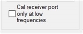
For any channels that are 1) Split Port Cal (SMC/GCX/MODX), 2) Cal Receiver Port Only at Low Frequency (banded noise only), or 3) Independent Calibration Channels, note the following:
Note: Some channels do not support setting the cal power level. If this is the case, then the field will be disabled. On the last Cal All Wizard page, the Description column specifies whether the channel is being calibrated by Cal All or performing its own calibration: If it is being calibrated by Cal All, it displays which Cal All channel is performing the calibration. Note: If a user chooses to Enable Extra Power Cals, then the only client channels that are participating in Cal All as normal will inherit the corresponding power calibration terms (this is most often used with SA, which cannot be an Independent Calibration Channel). |
|
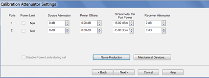
This dialog shows the Power, Attenuator, and IFBW settings for the Cal All calibration. The default values for the Cal All session are the preset values of a standard S-parameter channel. These values are not necessarily the same as those of the channels that are selected for calibration. When there are differences in measurement path (switch) settings between the Cal All channel and the selected channels, these differences are detected by Cal All and additional measurements are made for each path condition. These additional measurements allow Cal All to produce error terms appropriate for each of the selected channels. In general, the Cal All session should be performed at a power level that is high enough to prevent noise in the error terms. However, an increase in power could cause compression or damage to the analyzer receivers. The following settings allow you to increase the power level ONLY during the Cal All session. Note: The following settings do not apply to Independent Calibration Channels. Those calibrations are performed using the power and attenuation settings as configured in the channel. Power Limit (Disable) Cal All shows you when power limits are enabled. This setting provides you a convenient way to TEMPORARILY disable these limits in order to take advantage of the power settings available in Cal All. If power limits are on, your DUT is probably a high-gain device and the attenuator settings in your channels are high resulting in lower power at the cal reference plane. This lower signal can result in noisier measurements during the acquisition of cal. This situation is precisely what Cal All is intended to improve. Cal All allows you to configure the calibration conditions for better signal-to-noise performance during the cal while leaving your DUT conditions alone. You can elect to clear the “Disable Power Limits during cal” checkbox when you prefer to calibrate at a higher power level than is allowed by your limit. The limit is restored after the Cal All session. Source / Receiver Attenuator By default, the Cal All calibration is performed with Source and Receiver attenuators set to 0. Change the Source or Receiver attenuator settings when external hardware (such as a booster amplifier) would cause the analyzer receivers to be compressed or damaged. You may also want to change the attenuator or path configuration settings to force the cal channel to match settings of the selected channels. If all of the selected channels are set to identical hardware settings, it may be better to apply these settings to the cal channel. For example, if your channels all use a 5 or 10 dB attenuator step at port 1, you might elect to change the Cal All channels to use the same low attenuator settings. This will result in the cal measurements being made under the same path conditions as the channel and it will eliminate the need to mathematically compensate for the difference. However, if large attenuator values are used, the default Cal All settings will likely improve your results. S-Parameter Cal Port Power Set the power level at which the S-Parameter cal is performed. Power Offsets Power Offsets are channel-scoped. Consequently, offsets that you already set are NOT automatically copied to the Cal All session. This setting allows you to also apply a Power Offset during the Cal All session. Learn about Power Offsets. This button accesses the following dialog for settings that help reduce trace noise and the noise floor which can lead to better dynamic range and more accurate measurements. Learn more.
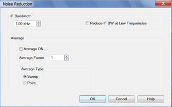
Set the IFBW used to perform the Cal All calibration. The default IFBW setting of 1 kHz is a good nominal setting for most measurements. Lowering the IFBW removes noise from the calibration measurement, but also causes slower sweeps. Always ON Check to enable averaging. Average Factor Specifies the number of measurements that are averaged. Range of 1 to 65536 (2^16). Average Type Sweep Each data point is based on the average of the same data point measured over consecutive sweeps. (Sweep) Restart Begins a new set of measurements that are used for the average. Applies only to Sweep averaging - NOT Point. Point Each data point is measured the number of times specified by the Average Factor, and then averaged, before going to the next data point. Reduce IF BW at Low Frequencies When this box is checked, the VNA uses a smaller IF Bandwidth than the selected value. Learn more. Note: [M983xA] Turning ON makes the sweep slower. Turn OFF and select the proper IF BW manually could save the sweep time. |
For each DUT port:
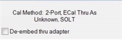
Check Modify Cal to change the Thru method. An Unknown Thru cal is performed by default. Learn about THRU methods. |
|
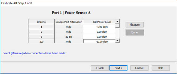
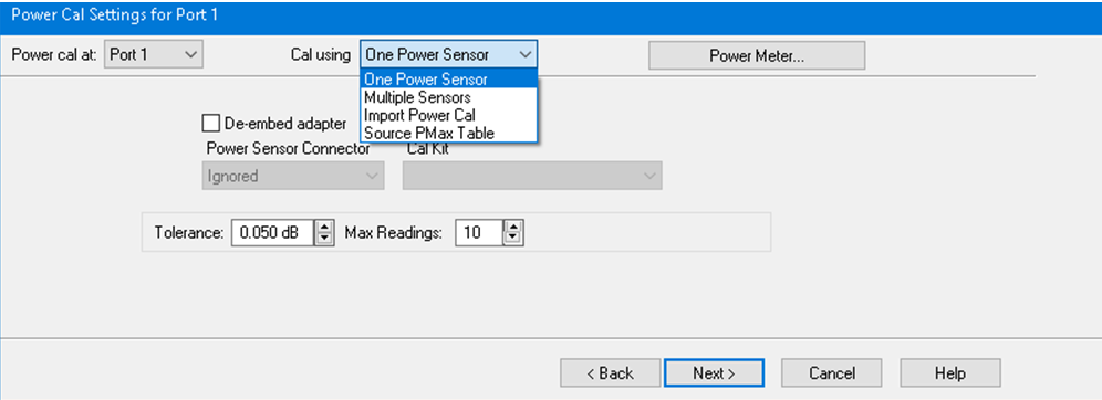
A guided power cal is performed on the source ports for the Cal All calibration. This dialog is displayed for each source port to receive a power cal. To perform an LO power cal for a mixer channel, set the LO port to a VNA or external source in the Mixer Setup dialog. Then select that port in the Selected Channels dialog.
|
|
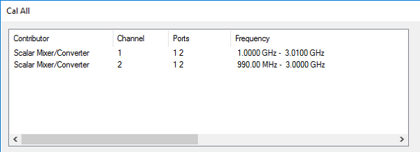
This page is a summary of the Cal All settings. Confirm the settings, then click Next > or < Back to change settings. |
|
Follow the prompts to connect each standard. Then click Measure. Click Re-measure if necessary. Then click Next >
|
|
Click Finish to save the Cal All session results to Cal Registers. Or click Save As User CalSet, then enter a prefix title. The Meas Class and channel number are appended to this prefix to save to a User Cal Set for each calibrated channel. |