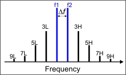
Two main tones (f1 and f2) with odd order intermodulation products.
Swept IMD for Converters (separate topic)
When a device or system is subjected to multiple input frequencies, the non-linearity of the DUT can generate undesired outputs at other frequencies. Typically, two input tones of equal power separated in frequency by a specified amount are used to stimulate the device while observing the resulting frequency spectra at the output. A variety of measurements can then be utilized to determine the intermodulation distortion characteristics of the device.
The frequencies of the resulting distortion products are predictable. While many mixing products can be generated, the high and low signals of the "odd order" products (3rd, 5th, and so forth) are close enough to the original two signals to potentially interfere with adjacent communication channels. With the exception of the 2nd order product, the higher "even order" products are usually far enough away to be of no interest.
The following image and table shows two equal-power main-tones and the nearby odd-order distortion products, as well as the 2nd order product (not shown in the image). Notice that the frequency separation between adjacent odd-order products is the same as the separation of the main tones (Delta F) frequency. For most devices, these distortion products become worse as the device is pushed further into compression.
|
Two main tones (f1 and f2) with odd order intermodulation products. |
The following table shows the calculations and example frequencies (Blue text) of the intermodulation products that are closest to the two main tones.
Product |
Low (L) |
High (H) |
Main |
f1 100 MHz |
f2 120 MHz |
3 |
2f1-f2 80 MHz |
2f2-f1 140 MHz |
5 |
3f1-2f2 60 MHz |
3f2-2f1 160 MHz |
7 |
4f1-3f2 40 MHz |
4f2-3f1 180 MHz |
9 |
5f1-4f2 20 MHz |
5f2-4f1 200 MHz |
2 |
f2-f1 20 MHz |
f1+f2 220 MHz |
Learn about Swept IMDx for Converters Concepts
The following basic parameters, offered for both Amps and Converters, are expanded to over 150 by selecting specific product tones (2,3,5,7,9), the Low-side, High-side, or Average of these tones, measured at the Input or Output of the DUT.
Learn how to select these IMD parameters.
Tone Power parameters measure the absolute power level of the main tones, odd-order product tones up to the 9th order, and the 2nd order product tones. These tone powers can be measured at the input and output of the DUT. Because the tones come in pairs, the Low tone, High tone, and the Average of the two can be measured and displayed.
The Average Tone Power is calculated as follows:
Avg = (High tone (dBm) + Low tone (dBm) ) / 2
When measuring the 2nd order products, only the Low tone and High tones are allowed. When the main tones are separated by less than 10 MHz, the Low tone (f2-f1) is below the frequency range of the VNA.
Tone Gain (in dB) calculates the main tone Output Tone power / Input Tone power. Because the tones come in pairs, Tone Gain can be calculated for the Low tone, High tone, and the Average of the two as indicated in the Average Tone Power calculation.
For IMDx for Converters, the Input and the Output tones are typically at different frequencies.
IMD parameters measure the difference in power level between the specified product tone and the main tones. These IMD parameters are calculated from the Tone Power measurements. IMD parameters can measure the odd-order product tones up to the 9th order, and the 2nd product tones, at the DUT Input or Output. For each specified product, the difference between the Low product and main tone, difference between the High product and main tone, and difference between the Averages of the product and main tone can be measured and displayed.
Swept IMD supports IMD parameters which are calculated as follows:
IMxLo = IMxHi = IMx = IMxLoIn = IMxHiIn = IMxIn = |
PwrxLo-PwrMainLo PwrxHi-PwrMainHi Pwrx-PwrMain PwrxLoIn-PwrMainLoIn PwrxHiIn-PwrMainHiIn PwrxIn-PwrMainIn |
where:
x = the IM product of interest (2, 3, 5, 7, 9)
Avg is implied if Hi or Lo is not stated
Output is implied when In is not stated
Learn how to select IMD parameters.
As the main tone output power increases (black arrow), output power in the specified product tone increases at a predictable, and steeper, rate (green arrow). At some point, the power in the product tone will be equal to the power in the main tone. The power level at which this occurs is known as the intercept point. Measuring this point directly is typically not possible. Therefore, it is calculated by measuring the main tone power and the specified product tone power.
The Swept IMD App can display either the DUT Input power or DUT Output power that is required to achieve the theoretical intercept point. This is called either Input Referred (IIP) or Output Referred (OIP).
This measurement can be made for the 2nd, 3rd, 5th, 7th, and 9th order intercept points. In addition, the measurements can be made for either the Low tone, the High tone, or the Average of the two. However, for the 2nd order intercept point, only Low and High tone parameters are supported; not Average.
Swept IMD supports Intercept Point parameters which are calculated as follows:
OIPxHi = OIPxHiIn = OIPxLo = OIPxLoIn = OIPx = OIPxIn = IIPxHi = IIPxHiIn = IIPxLo = IIPxLoIn = IIPx = IIPxIn = |
PwrMain - IMxHi/(x-1) PwrMain - IMxHiIn/(x-1) PwrMain - IMxLo/(x-1) PwrMain - IMxLoIn/(x-1) PwrMain - IMx/(x-1) PwrMain - IMxIn/(x-1) PwrMainIn - IMxHi/(x-1) PwrMainIn - IMxHiIn/(x-1) PwrMainIn - IMxLo/(x-1) PwrMainIn - IMxLoIn/(x-1) PwrMainIn - IMx/(x-1) PwrMainIn - IMxIn/(x-1) |
where:
x = the IM product of interest (2, 3, 5, 7, 9)
PwrMain = average power of the main tones at the DUT Input or Output
IMx = product tone power - main tone power (from above IMD parameter)
Avg is implied if Hi or Lo is not stated
Output is implied if In is not stated
Learn how to select IMD parameters.
From the NCTA Standard, composite triple beat is defined as the modulation beat of the target channel signal caused by triple beat resulting from the nonlinear characteristic of the DUT. Composite triple beat is expressed as the ratio of the target channel signal level to the maximum mean level of beat components dispersed around the carrier of that target channel.
Swept IMD supports two parameters of this type:
CTB is based upon an approximation for the number of beats in mid-band
CTBE is based upon an approximation for the number of beats at the band edge.
The equations for these two parameters are as follows:
Mid-Band CTB(dB)=-2(Pi-Ps)+6+10Log(3N2/8)+CTB Offset
Band Edge CTBE(dB)=-2(Pi-Ps)+6+10Log(N2/4)+CTB Offset
Where:
Pi = Output power level at the third order intercept point (dBm): OIP3 (Lo | Hi)
Ps = One of the following values based upon the Composite Normalization Mode:
For PDBM or PDBMV mode, Ps = CompositeNormalizedCTBPower
For Number of Carriers mode, Ps = PwrMain (AVG) – 10Log(N/2)
For None mode, Ps = PwrMain (AVG)
CTB OFFset = Offset value for CTB calculation
N = Total number of carriers.
Note: CTB OFFset and N values can ONLY be set using SCPI or COM commands.
Learn how to select IMD parameters.
From the NCTA Standard, composite second order is defined as the modulation beat of the target channel signal caused by second order beat resulting from the nonlinear characteristic of the DUT. Composite second order beat is expressed as the ratio of the target channel signal level to the maximum mean level of beat components dispersed around 0.75 MHz and 1.25 MHz above and below the carrier of that channel.
Swept IMD supports a CSO parameter which is calculated as follows:
CSO(dB)=(Pi-Ps)+10Log(N)+CSO Offset
Where:
Pi = Output power level at 2nd order intercept point: OIP2 (Lo | Hi)
Ps = One of the following values based upon the Composite Normalization Mode:
For PdBm or PdBmV mode, Ps = CompositeNormalizedCSOPower
For Number of Carriers mode, Ps = PwrMain (AVG) – 10Log(N/2)
For None mode, Ps = PwrMain (AVG)
CSO OFFset = Offset value for CSO calculation
N = Number of distortion products.
Note: CSO OFFset and N values can ONLY be set using SCPI or COM commands.
Learn how to select IMD parameters.
From the NCTA Standard, cross modulation is defined as the distortion that causes modulated carrier components of undesired channels to amplitude-modulate the target channel carrier due to the nonlinear characteristic of the unit under test. Cross modulation distortion is expressed as the ratio of the target channel carrier level to the level of modulated components of the carrier of the target channel resulting from modulated signals of undesired channels.
Swept IMD supports an XMOD parameter which is calculated as follows:
XMOD=-2(Pi-Ps)+6dB+20Log(N)
Where:
Pi = Output power level at third order intercept point: OIP3 (Lo | Hi)
Ps = Power level of each carrier: PwrMain (AVG)
N = Total number of carriers.
Make Cross Modulation settings using SCPI or COM commands.
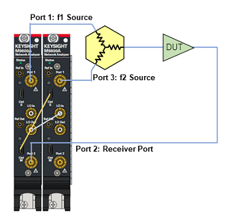
The following diagram illustrates how the VNA is configured to generate the two main tones.
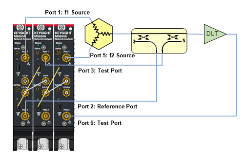
DRA configuration for ports 1 to 3 is required.
Note: Above 40 GHz, high pass filter to block 2/3 sub-harmonics is required. Low pass filer to block 4/3 sub-harmonics is recommended.
Depending on the specified parameters and sweep type, the sources and receivers are tuned to the appropriate frequencies in order to measure all of the required main and product tone powers. For example, an IM3 parameter requires the measurement of both main tones, and the 3rd order High and Low tone powers.
Use appropriate IFBW and tone space to satisfy the following condition.
20 × Log((2 IFBW [Hz] )/(π (x-1) ToneSpace [Hz]))<IMx[dBc]-20 [dB]
20 × log(IFBW [Hz] / tone space [Hz] / π) < IMx [dBc] – 20 dB
Because the main tones are generated by the VNA internal sources and external sources, the frequencies of the main tones must always be within the frequency range of the VNA or external source. Sweep parameter values are adjusted when necessary to ensure that f1 and f2 frequencies are within these limits.
However, the VNA DOES allow you to make settings that cause the selected IM products to fall outside the frequency range of the VNA. For example, with the main tones at 10 MHz and 15 MHz, the VNA will allow you to select the parameter IM3Lo (3rd low side product tone). However, the frequency of this product will be at 2f1-f2 or 5 MHz, which is below the frequency range of the VNA. In these cases, the trace data is set to zero, which converts to -200 dB in Log Mag format.
The total number of acquisitions per sweep can not exceed 10,003 points. The number of acquisitions is determined by multiplying the number of trace points, by the number of tones frequencies, then by 2 (for both Input and Output frequencies). The VNA will automatically reduce the number of trace points to ensure the total number of acquisition points does not exceed 10,003.