Swept IMD for Amplifiers (Opt S9x087A/B)


Other IMD (Opt S9x087A/B) Topics

Features and Limitations

See requirements.

Features

Limitations

The following features are NOT available with Swept IMD:

Create a Swept IMD Measurement

  1. Press Meas > S-Param > Meas Class....

  2. Select Swept IMD, then either:

  1. A Swept IMD measurement is displayed. To select additional parameters to display, click Response, then Meas, then select a parameter from the list.

How to start the Swept IMD Setup dialog

Using Hardkey/SoftTab/Softkey

Using a mouse

  1. Press Freq > Main >  IMD Setup....

  1. Click Stimulus

  2. Select IMD Setup...

Frequency tab - IMD Setup dialog box help

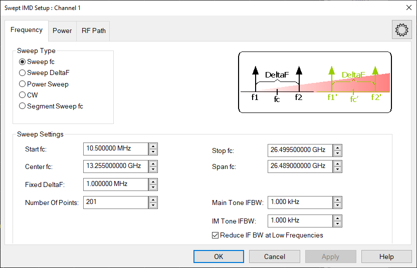
Configures the Sweep Type and frequency range for SweptIMD and Swept IMDX measurements.

Sweep Type and Sweep Settings

Sweep fc (center frequency)

Maintaining a constant tone spacing (Fixed DeltaF) and tone power, fc is swept from Start fc to Stop fc. Center Frequency can also be specified as Center fc and Span fc.

At each fc, the receivers are tuned to all of the required frequencies to measure the power of the appropriate tones.

Swept DeltaF (tone spacing)

The specified fc (center frequency) and tone power is held constant. The tone spacing is increased from Start DeltaF to Stop DeltaF in the specified number of points.

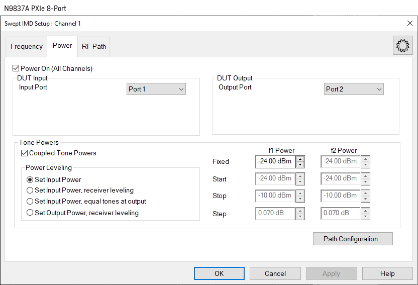
Power Sweep

The main tone frequencies are specified as either f1 and f2, or as fc and DeltaF. These frequencies are held constant while the power of each main tone is varied from the Start-Power to Stop-Power in the specified number of power points. The power of each tone can be set (on the Power tab) individually or as a pair by checking Coupled Tone Power.

CW

The main tone frequencies and power levels are held constant. Measurements are taken for the specified Number of Points. The X-axis is number of points.

Segment Sweep fc (Swept IMD ONLY)

Same as Sweep fc except that the center frequencies are constructed using the standard segment table. Learn how.

LO Power Sweep (Swept IMDX ONLY)

The main tone frequencies and power levels are held constant. Measurements are taken for the specified number of points. The X-axis is LO Power.


Segment Sweep Notes: (Swept IMD ONLY)

Number of Points  Enter the number of data points for each sweep. See Limited Number of Acquisitions.

IFBW

The Narrowband IF path is used for IMD measurements to help reduce spurious responses. Because the narrowband filter has a bandwidth of about 28 kHz, using an IFBW greater than 30 kHz does nothing to improve measurement accuracy.

Main Tone and IM Tone IFBW  IF Bandwidth is specified separately for the main tones (f1 and f2) and for the intermodulation tones. This allows the higher-power main tones to be accurately measured at a higher - and faster - IFBW, while the lower-power product tones to be accurately measured a lower - and slower - IFBW.

Note: The IFBW is limited to 600 kHz when performing Swept IMD measurements even if the Wide IF path is selected.

Reduce IF BW at Low Frequencies - On the VNA,  the trace noise becomes worse below 748 MHz. This is especially obvious between 10 MHz and 45 MHz. When this box is checked, the VNA uses a smaller IF Bandwidth than the selected value at frequencies below 748 MHz. Learn more about the selected values.

Note: For Main Tone IFBW settings of 1 kHz and below, and when the center frequency of the VNA is an exact multiple of 10 MHz, then the tone frequencies are shifted UP by (10* IFBW) for the entire IFBW sweep. If those frequencies would exceed the maximum frequency of the analyzer, then the frequency is shifted DOWN by (10 *IFBW). This is done to avoid interference with 10 MHz reference signals.


Power tab - IMD Setup dialog box help

Configures RF power and Power Sweep settings for IMD measurements.

Power ON (All channels)  Check to turn RF Power ON or clear to turn power OFF for all channels.

DUT Input Port

Input Port  Choose the port  (DRA port) for DUT input

Source Attenuator  Specifies the port 1 attenuator. This attenuator affects the range of available power into the DUT Learn more about Source Attenuation.

Receiver Attenuator  This attenuation setting protects the A receiver from damage.

DUT Output Port

Output Port  Choose the port for DUT  output.

Source Attenuator  This setting is used to improve the load match at the DUT output. Select 0 dB for power levels up to 10 dBm, and increase by 10 dB for every 10 dBm more output power.

Receiver Attenuator  Specifies the attenuator setting for port 2. When the power into the receiver test port is around +10 dBm, the VNA receiver may be in compression. However, with receiver attenuation, lower input power levels may become too noisy to make accurate power measurements. In this case, lower IFBW for the IM tones to reduce noise.  Learn more about Receiver Attenuation.

Tone Powers

Coupled Tone Power  Check to set the same power level for each main tone using the f1 Power setting. Clear to set different f1 and f2 power levels.

ALC On  Check to use internal ALC hardware (default). Clear to use Open Loop hardware. Open Loop leveling should only be used when doing Wideband Pulse measurements.

Power Leveling

Because the gain of the DUT can be different for the f1 and f2 tone frequencies, you can set tone power at either the input of the DUT OR the output using the following methods. Receiver Leveling will cause slower sweeps.

Set Input Power (Default) The specified f1 and f2 power levels are set at the DUT input.  Input power level accuracy is based ONLY on the source power cal that is performed during the IMD cal. The input and output tones may NOT be equal or flat.

Set Input Power, receiver leveling  The specified f1 and f2 power levels are set at the DUT input using receiver leveling at the input reference receiver. This ensures the tone power levels are equal at the DUT input.  However, the output tones may NOT be flat due to variations in the gain of the DUT at different frequencies.

Set Input Power, equal tones at output  The specified f1 and f2 power levels are set at the DUT input and a measurement is made at the output. The inputs are adjusted once at each frequency to ensure the tone power levels are equal at the DUT output.  However, the output tones may NOT be flat due to variations in the gain of the DUT at different frequencies.

Set Output Power, receiver leveling  The specified f1 and f2 power levels are set at the DUT output.  Receiver Leveling at the output receiver is used to accurately set the specified power level of each tone within the tolerance value that is set in the Receiver Leveling dialog. This setting results in the output tones being equal and flat across the frequency range.

Note: Enabling Safe Mode when using receiver leveling may be necessary to ensure stable results.

f1 / f2 Power

Fixed f1 Power  Specify the power level for f1 at either the DUT input or output depending on the Power Leveling setting. Choose a value between -30 dBm and +30 dBm. When "Coupled Tone Power" is checked, power is set for both f1 and f2 tones.

Fixed f2 Power  Available when Coupled Tone Power is NOT checked. Specify the power level for f2 at either the DUT input or output depending on the Power Leveling setting. Choose a value between -30 dBm and +30 dBm.

Start, Stop, and Step f1 and f2 Power  Available when Power Sweep is selected on the Frequency tab. Sets the Start and Stop power levels for f1 and f2, either individually or together with Coupled Tone Power checked.

Highlighted Note: RF2 tone power offset to compensate for combiner loss.

This message appears when the f2 tone is being supplied by an external source. The tone power has been increased on the external source to compensate for loss through the internal combiner. For example, if the tone power at the DUT should be 0 dBm, the power out of the source will be about 15 dB higher.


Configure tab- IMD Setup dialog box help

Receiver Configuration

Note: Multiple Receiver Configurations is a Licensed Feature. Learn more about Licensed Features.

Internal Combiner Using One Ref Receiver - This configuration is supported on the PNA-X only and is the default mode. This configuration is one reference receiver + internal combiner mode.

External Combiner Using One Ref Receiver - This configuration is one reference receiver without internal combiner on the PNA-X. For PXIe, the configuration is DRA mode IMD.

Source Configuration

To accommodate single-source VNA models, an external source can be used for the f2 tone.

Learn how to configure an external source and combiner to make Swept IMD and IMDx measurements.

f1  Always uses VNA internal source 1.

f2  Select a source to be used for the f2 tone. This selection is available when an external source is configured and the Active box is checked on the External Source Configuration dialog.

Hardware Configuration

Add Source  Click to configure an external source using the External Source Configuration dialog.


How to add IMD Parameters

Using Hardkey/SoftTab/Softkey

Using a mouse

  1. Press Trace, then select trace.

  2. Press Meas, then select a parameter.

  1. Click Instrument, Trace, Add Trace.

  2. Click Response, Meas, then select a parameter.

IMD New Trace dialog box help

Use this dialog to select IMD and IMDx parameters to measure and display.

Up to five parameters can be selected at a  time, then click Apply to create those traces. Then select more without closing the dialog. There is no limit to the number of traces and windows allowed in the VNA.

Note: Calculations are NOT performed to determine if the frequency of a selected intermod (Order) product will be within the frequency range of the VNA. Measurements that fall outside of the frequency range of the VNA are displayed as -200 dB.

Param Name  This name is built from the selected Type, Tone Select, Order, and Measure At settings. Once built, check to measure this parameter.

Note: For PXI, M960X PXI SMU is supported.

Type

Select the type of Swept IMD measurement to make.

The characters below (in parenthesis) are used in the Param Name.

  • Tone Power (Pwr)  Measures the absolute power of the specified (ordered) tone. Learn more.

  • IMD Relative to Carrier (IM)  Measures the power of the specified (ordered) tone relative to the power of the f1 or f2 tone. Learn more.

  • Input Referred Intercept Point (IIP)  From DUT measurements, calculates the theoretical power level at which the specified (ordered) intermod product will be the same power level as the carrier at the output of the DUT. The input power to the DUT at which this output power occurs is reported and displayed. Learn more.

  • Output Referred Intercept Point (OIP)  From DUT measurements, calculates the theoretical power level at which the specified (ordered) product will be the same power level as the main tone at the output of the DUT. This value is reported and displayed. Learn more.

  • CTB Band-Edge Distortion (CTBE)   Composite 'Triple Beat' Distortion - 3rd order DUT OUT only. Learn more.

  • CTB Mid-Band Distortion (CTB)   Composite 'Triple Beat' Distortion - 3rd order DUT OUT only. Learn more.

  • CSO Distortion (CSO)  2nd order DUT OUT only. Learn more.

  • XMOD 3rd Order Crossmod (XMOD)   3rd order DUT OUT only. Learn more.

  • Tone Gain (ToneGain) From tone power measurements, calculates the Output Tone power / Input Tone power for the specified tones. Learn more. The Input and Output tones are different frequencies.

  • Gamma Measures receiver ratios to compute input match of the DUT or load match seen at the output of the DUT. For example, when using port 1 for DUT input and port 2 for DUT output, GammaIn = b1/a1,1 and Gamma = a2/b2,1. Under Correction Methods, requires Power Correction Type = Actual Waves, and the box checked for Enable 8-term Error Correction Model. Learn more.

  • AI1  Analog input pin on the Power I/O connector.

  • AI2  Analog input pin on the Power I/O connector.

  • AIG  Analog ground (common) pin on the Power I/O connector.

  • AOS1  DC output, AUX OUT 1.

  • AOS2  DC output, AUX OUT 2.

Tone Select

Select the tone (High, Low, or Both) to be measured and displayed (See image).

  • High  Measure and display the power of the specified (ordered) tone on the High side of the main tones.

  • Low  Measure and display the power of the specified (ordered) tone on the Low side of the main tones.

  • Avg  Measure the specified (ordered) tones on both the High and Low sides. Then calculate and display the Average power level.  Note: The Avg power level is actually the mean dB value of the high and low side tones - NOT the true average power level which would be calculated from linear power (watts).  This is done to be consistent with the Power Leveling algorithm that is used to set the tone powers equal at the DUT input or output, which is also based on the dB values.

  • Max  Measure the specified (ordered) tones on both the High and Low sides. Then find and display the Maximum power level.

  • Min  Measure the specified (ordered) tones on both the High and Low sides. Then find and display the Minimum power level.

Used to build the parameter name:

  • Hi, Lo, Max, and Min are appended to the Param Name when selected.

  • Nothing is appended to the Param Name when Avg (default setting) is selected.

Important Notes - 2nd-order products

  • 2nd-order products are likely to be outside of the VNA frequency range. When that occurs, trace data will show all zeros (linear) or -200 dB (log magnitude).

  • If either the High or Low side falls outside the frequency range of the VNA, then Avg is NOT allowed.

  • When displaying 2nd-order traces, Avg is NOT allowed, even when both the Lo and Hi products are displaying valid data. This is because 2 Low and 2 High products are usually very different from one another.

  • When performing a calibration that is meant to include 2nd-order products, be sure Include 2nd Order Products is checked in the first Calibration dialog box.

Order

Specify the intermodulation product to measure. Choose from 1, 2, 3, 5, 7, 9.

  • Main is appended to the Param Name when 1 is selected.

  • Otherwise, the tone number is appended to the parameter name.

Measure At

Measure the selected parameter at either:

DUT Input

  • In is appended to the Param Name (ex: PwrMainIn).

  • The input port reference receiver is used to measure the fundamental tones and the required products.

DUT Output

  • Nothing is appended to the Param Name (ex: PwrMain).

  • The output port measurement receiver is used to measure the fundamental tones and the required products.

IMD Calibration

Overview

  1. At the first page of the IMD Cal Wizard, you tell the calibration routine the frequencies at which the calibration is to be performed. Optionally, you can choose to perform the source power cal at only the center frequency midway between the main tones. For IMDx ONLY, you can also choose to perform a source power cal of the LO source.

  2. The VNA calculates an array of source and receiver frequencies that incorporate all the main tone frequencies (low and high) and the specified product tone frequencies.

  3. Using a power meter at port 1, a source and receiver calibration is performed to calibrate the R1 reference receiver to be a fast and 'tunable' power meter.  

  4. The R1 reference receiver is then used to perform a source power cal of the main tone frequencies: first the Source 1 / Low tone then the Source 2 / High tone. Both sources are left ON while each tone is measured in order to duplicate the impedance match under which the measurement will be performed.

  5. Then a standard 2-port SOLT cal is performed at all frequencies using either an ECal module or mechanical standards. The 2-port cal is used to correct the source calibration R1 tracking terms for the match of the power sensor.  It is also used to transfer the R1 tracking term to the B receiver.

Notes

External Combiner Using Two Reference Receivers Calibration

The Cal All wizard supports calibration of the two reverence receiver configurations (external combiner and combiner in DUT).

  1. In the Configure tab, select External Combiner Using Two Ref Receivers:

  2. Press Cal > Other Cals > Cal All.... The Calibrate All Selected Channels dialog is displayed:

  3. Receiver Calibration: Connect the power sensor to the Cal Plane (Cal Plane is the output of the external combiner). The R1 and R3 receivers will be calibrated with the power sensor.

  4. Source Calibration: After the R1 and R3 receivers are corrected, both Port 1 and Port 3 are turned on, then Port 1’s source is calibrated with corrected R1 and Port 3’s source is calibrated with corrected R3.

  5. S-Parameter Calibration: Because Port 1 and Port 3 share one Cal Plane, Thru 1-3 is removed by the software and only keeps two Thrus:

  6. The following shows an actual measurement with leveling turned on.

See Also

IM Spectrum Calibration


How to start a Swept IMD Calibration

Using Hardkey/SoftTab/Softkey

Using a mouse

  1. Press CAL > Main > Smart Cal....

  1. Click Response

  2. Select Cal

  3. Select Smart Cal...


Select Tone Products - IMD Cal dialog box help

Calibration Mode

Match corrected Response Cal  This selection performs a full IMD calibration as described in the above Calibration 'Overview'.

Response ONLY (Normalization)  This IMD Cal does NOT correct for the mismatch of the power sensor.  Choose this if you have a test configuration that does not easily accommodate making match measurements.  Instead of a standard 2 port SOLT cal (Step 5 above), only the transmission tracking term is measured and used to transfer the R1 receiver tracking term (produced by the power sweep) to the B receiver.

Note: For the Response (Normalization) Cal, it is assumed that a zero-length THRU standard is being used to connect port 1 to port 2. If an adapter is used, there is NO compensation for delay or loss of the adapter. This can NOT be changed.

Tone Power Cal

Calibrate only at center frequencies  The source power cal portion is performed at only the center frequency, which is midway between the main tones. This cuts the source power calibration time (the slowest part of the calibration) in half. The measurement is interpolated although the C* annotation is not shown in the status bar.

Calibrate at all frequencies The source power cal portion is performed at all main tone frequencies.

Enable LO Power Calibration  (IMDx ONLY) Check to perform a standard power calibration of the LO source as part of the calibration process.

Select Product Tones

Max Product  Select the highest product that you will be measuring. The low and high frequencies for that product, and all lower 'odd' order products will be calibrated. For example, when 5th Order Product is selected, the frequencies for the Main Tones, and the Low and High order products for the 3rd and 5th order products will be included in the calibration.

Include 2nd Order Products  Check to calibrate the 2nd-order products in the frequencies to be calibrated.  The frequencies of these products are usually far from the main tones.

Extrapolated ECal Calibration

A Preference setting can be made which allows a Swept IMD and IMDx calibration to exceed the stop frequency limit of an ECal module. The error terms beyond the ECal stop frequency are extrapolated.

The setting is designed to provide correction for order products (especially 2nd order) when the frequencies exceed the ECal module stop frequency.

  • The accuracy of the extrapolated error terms is not as good as those that were measured.

  • This feature is NOT allowed when using Cal All Channels.

  • The ECal Extrapolation state and frequencies are saved to the Cal Set and visible in the Cal Set Properties dialog.


Select DUT Connectors and Cal Kits - IMD Cal dialog box help

If Response Only is selected on the previous page,  click Source Cal Settings... to change the Source Cal settings, or click Next> to continue.

Otherwise, this is a standard VNA Cal Wizard page except for the following:

Modify Cal  Check, then click Next, to Modify Cal (Standards AND Thru Method).

Source Cal Settings  Click to launch the Source Cal Settings (for Apps) dialog.

Learn more about IMD Calibration


Power Cal Settings - IMD Cal dialog box help

A power calibration is performed on port 1. This is done to simplify subsequent IMD calibrations since the power calibration will not need to be repeated.

For highest accuracy, connect the power sensor directly to the test port with no adapter.

Learn more about these settings.


IMD Calibration Step 1 dialog box help

Power Level at which to perform the Port 1 Source Power Cal.

It is usually best to perform the Source Power Cal at 0 dBm because the power sensor is calibrated at that level.

However, if a component is used between the VNA source and the calibration reference plane, then adjust the power level so that the power at the sensor is about 0 dBm if possible.

Learn more about IMD Calibration

The remaining dialog pages are the same as the standard Cal Wizard.

Saving Swept IMD Power Data

Swept IMD power data, Log Mag ONLY, can be saved to a *.csv file. This data type can be read by spreadsheet programs, such as Microsoft Excel.  Data from the last complete sweep is saved to the specified *.csv file.

How to save Swept IMD (and IMDx) data

With a Swept IMD or IMDx channel active...

Using Hardkey/SoftTab/Softkey

Using a mouse

  1. Press Save  Recall > Save Other > Save Data....

  2. File Type= CSV Formatted Data (*.csv).

  1. Click File

  2. Select Save Data
  3. File Type= CSV Formatted Data (*.csv).

Notes:

This image shows the 6 Main tone power levels that are always saved.

In the power parameter labels, Output and Avg are implied as in the parameter selection. For example: PwrMain = Average Output power of the main tones.