Adjacent Channel Leakage Ratio (ACLR) Measurement Description
Last updated: January 16, 2009
- How is an Adjacent Channel Leakage Ratio Measurement Made?
- Adjacent Channel Leakage Ratio Measurement Parameters
- Adjacent Channel Leakage Ratio Input Signal Requirements
- Adjacent Channel Leakage Ratio Measurement Calibration
How is an Adjacent Channel Leakage Ratio Measurement Made?
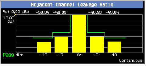
Adjacent channel leakage ratio (ACLR) measures the relative power at ± 5 MHz and ± 10 MHz offsets from the uplink channel. Power is measured through a Root-Raised Cosine (RRC) filter with a rolloff of a=0.22, and a bandwidth equal to the chip rate (3.84 MHz). The ± 5 MHz measurements are referred to as the upper and lower first adjacent channels; the ± 10 MHz measurements are referred to as the upper and lower second adjacent channels. This measurement is defined in 3GPP TS 34.121, sections 5.10 and 5.10A, Adjacent Channel Power Leakage Ratio (ACLR).
Measurements for individual offsets can be turned off to increase measurement speed when these measurements are not needed.
Measurements can be displayed in either numeric or graphical form. When the graphical display is used (shown below), limits can be set for each offset to form a "limit line." When a limit is exceeded, the status changes from "Pass" to "Fail."

Adjacent Channel Leakage Ratio Measurement Parameters
- Multi-Measurement Count: (see Statistical Measurement Results ).
- -5 MHz Offset State
- +5 MHz Offset State
- -10 MHz Offset State
- +10 MHz Offset State
- Trigger Arm: (see Trigger Arm (Single or Continuous) Description ).
-
Trigger Source
You must specify how you want to trigger the measurement using the
Trigger Sourcesetting.You may set
Trigger Sourceto the following: (for more information on these trigger types, see Trigger Source Description ).-
Auto: if the UE is synchronized to the test set, it uses protocol triggering; otherwise, it uses immediate triggering.
-
External
-
HS-DPCCH:
This setting is only applicable to the lab application or a feature-licensed test application.
When
Trigger Sourceis set toHS-DPCCH, you can specify on which uplink subframe the measurement triggers using the HS-DPCCH Trigger Subframe Alignment setting.Trigger Sourcecan only be set to HS-DPCCH when Channel Type =12.2k RMC + HSDPAor12.2k RMC + HSPA. -
Immediate
-
Protocol: Derived from the 10 ms downlink DPCH frame clock.
-
-
Trigger Delay
You can move the measurement interval (666.7 us = 1 timeslot) relative to the trigger using the
Trigger Delaysetting. -
HS-DPCCH Trigger Subframe Alignment
This setting is only applicable to the lab application or a feature-licensed test application.
When Trigger Source is set to
HS-DPCCH, you can specify on which uplink subframe the measurement triggers. You can then use the Trigger Delay setting to move the measurement interval (666.7 us = 1 timeslot) relative to that subframe boundary. - Measurement Timeout: (see Measurement Timeouts ).
Adjacent Channel Leakage Ratio Input Signal Requirements
- For this measurement the test set's receiver uses autoranging to adjust for the level of the signal being measured; therefore, the expected signal level does not need to be specified during measurement setup.
- The frequency of the signal being measured must be in the range of 800 MHz to 1000 MHz, 1700 MHz to 1990 MHz, or 2480 MHz to 2580 MHz.
- The level into the test set's RF IN/OUT connector must be in the range of +5 dBm to +28 dBm, in a 3.84 MHz bandwidth.
- The uplink must be of constant in-channel power for the duration of this measurement. This requirement has implications for correct power control configuration, and uplink dynamics in HSDPA and HSUPA.
Adjacent Channel Leakage Ratio Measurement Calibration
You must calibrate this measurement using the
Calibrate Measurements
procedure (see
Calibrating the Test Set
).
Related Topics
- Manual Operation: How Do I Make an Adjacent Channel Leakage Ratio (ACLR) Measurement?
- Programming an Adjacent Channel Leakage Ratio Measurement
- Adjacent Channel Leakage Ratio Troubleshooting
- What 3GPP W-CDMA/HSPA Conformance Tests Are Supported?
- Triggering of Measurements
- Statistical Measurement Results
- Integrity Indicator