Electrical Connector Care
Damage to electrical input connectors (as well as connectors on calibration and verification devices, test ports, cables, and other devices) can degrade measurement accuracy and damage instruments. Replacing a damaged electrical connectors can cost thousands of dollars, not to mention lost time! This expense can be avoided by observing the important precautions described in the topics referenced below.
To avoid expensive damage while making the final connection, select one of the following procedures for proper torque wrench and handling techniques. This guarantees a perfectly tight, consistent connections while preventing connector damage:
The drawings in this topic illustrate the proper handling of a torque wrench when making 1mm and 2.4 mm input connection. The general techniques can be applied to other connectors as well.
An N1060A module's 1mm and 2.4 mm input connectors are easily damaged by using improper connection techniques. To avoid expensive repairs to an N1060A, read this.
The input circuits can be damaged by electrostatic discharge (ESD). Therefore, avoid applying static discharges to the front-panel input connectors. Before connecting any coaxial cable to the connectors, momentarily short the center and outer conductors of the cable together. Avoid touching the front-panel input connectors without first touching the frame of the instrument. Be sure the instrument is properly earth-grounded to prevent buildup of static charge.
Connector Savers
Connector savers are useful in prolonging instrument life and ensuring better quality measurements. Refer to the following table for a list of commonly used connector savers.
| Connector | Part Number | Comments |
|---|---|---|
| 7 mm | Not available | |
| Type-N 50 ohm | Not available | |
| Type-N 75 ohm | 85036-60015 | Instrument grade |
| 3.5 mm | 85052-60013 | Metrology grade |
| 3.5 mm | 85059C | Instrument grade |
| 2.92 mm | 11904 | 2.4 to 2.92 adapters |
| 2.4 mm | 85056-60007 | Metrology grade |
| 1.85 mm | 85058-60009 | Instrument grade |
| 1.0 mm | Not available |
Do not twist one connector into the other (like inserting a light bulb). This happens if you turn the device body rather than the connector nut. Major damage to the center conductor can occur if the device body is twisted. Use open-ended wrenches on wrench flats on the outer bodies of the connector to help restrict rotation.
Apply force perpendicular to the wrench handle. This applies torque to the connection through the wrench. Do not hold the wrench so tightly that you push the handle straight down along its length rather than pivoting it, otherwise you apply an unlimited amount of torque.
Coaxial Connector Types
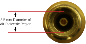
The following table shows commonly used RF coaxial connectors. N1055A 30/50 GHz TDR/TDT remote sampling head modules come with either 2.92 mm or 1.85 mm port connectors, depending on the option. With the exception of the SMA connector, connector types are identified by the diameter (in millimeters) of the air dielectric region as shown in this picture of a 3.5 mm connector.
| Connectory Type | Frequency Range | Coupling Torque | Compatible Connectors | Notes |
|---|---|---|---|---|
1.0 mm Connector |
≤ 110 GHz | 0.45 Nm (4 lb-in) |
1.0 mm | The smallest connector and is used on the N1060A Precision Waveform Analyzer module. This connector requires extra care to prevent expensive repairs and repair downtime when making connections. |
1.85 mm Connector |
≤ 70 GHz | 0.57 Nm (5 lb-in) |
2.4 mm | 1.85 mm and 2.4 mm connectors are intermateable. To aid identification, 1.85 mm Keysight connectors have a groove in the male nut and female shoulder. The outer thread size of 1.85 mm and 2.4 connectors is larger than the tread size on SMA, 2.92 mm, and 3.5 mm connectors. This makes the area of the outer conductor's mating surface appear very large compared to the relatively smaller air dielectric. |
2.4 mm Connector |
≤ 50 GHz | 0.9 Nm (8 lb-in) |
1.85 mm | |
2.92 mm Connector |
≤ 40 GHz | 0.9 Nm (8 lb-in) |
3.5 mm and SMA | 2.92 mm, 3.5 mm, and SMA connectors are intermateable. 2.92 mm and 3.5 mm connectors use the same center pin. Inserting the larger SMA (m) center pin into a 2.92 mm or 3.5 mm connector can slightly degrade the connector. It is recommended that you only mate SMA (m) connectors to other connectors that you reserve for this purpose. SMA connectors use a Teflon delectric. |
3.5 mm Connector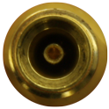 |
≤ 34 GHz | 0.9 Nm (8 lb-in) |
2.92 mm and SMA | |
SMA Connector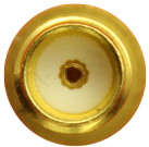 |
≤ 24 GHz | 0.9 Nm (8 lb-in) |
2.92 mm and 3.5 mm |