1.85 mm Connectors
This topic shows you how to properly connect, disconnect, and maintain 1.85 mm adapters and connectors.
Failure to follow the guidelines for proper connector handling and avoiding electrostatic discharge (ESD) can result in severe damage to the product. In some cases, the 1.85 mm connector is an integral part of the electrical sampler device. Therefore, by using improper cleaning and handling techniques, you risk expensive instrument repairs.
An Keysight 1.85 mm connector that is connected properly and well maintained should last for many years and many hundreds of connections. The best techniques for maintaining the integrity of your Keysight 1.85mm connector include routine visual inspection, cleaning, and proper connection techniques. If you fail to detect and remove dirt or metallic particles on a mating plane surface, you run the risk of degrading repeatability and accuracy. You also risk damage to any connector mated to it. Improper connections, resulting from pin depth values being out of the typical limits or from poor connection techniques, can also damage these devices. You should inspect the connector every time a connection is made. A connection made with a dirty or damaged connector can damage both connectors beyond repair. Magnification may be required to see damage on a connector. This is especially true with female connectors. Use a microscope with a magnification of 10x to inspect the connector mating surfaces. Also, you must use good lightning to see potential damage on a connector. For example, the contact fingers on slotted connectors may become bent or broken.
Not all defects that are visible only under magnification will affect the electrical performance of the connector. Some are the result of normal wear, such as mild spreading of female socket fingers or light burnishing of mating surfaces.
Examine and evaluate the integrity of the connector using the following guidelines:
- Obvious defects or damage. This includes badly worn plating exposing large amounts of base metal, deformed threads or bent, broken, or misaligned center conductors. Connector nuts should move smoothly and be free of burrs, rough spots, and loose metal particles. Loose metal particles have the potential to fall into the connector when it is disconnected and cause a short. Any connector that has obvious defects should be discarded or sent for repair.
- Mating plane surfaces. A good connection requires flat contact between the connectors at all points on their mating plane surfaces. Examine the connector mating plane surfaces for deep scratches, dents, dirt, and metal particles. Check the mating plane surfaces of the center and outer conductors for bent or rounded edges. Also look for signs of damage due to excessive or uneven wear or misalignment.
Inspecting for excessive, uneven wear or misalignment is especially important when mating a 1.85 mm connector to a 2.4 mm connector.
Light burnishing of the mating plane surfaces is normal and will appear as light scratches or shallow circular marks distributed uniformly over the mating plane surface. Other small defects and cosmetic imperfections are also normal. Light burnishing and minor defects will not affect electrical or mechanical performance. If a connector shows deep scratches or dents, particles clinging to the mating plane surfaces, or uneven wear, clean the connector and inspect it again. Try to determine the cause of damage before connecting a new, undamaged connector in the same configuration.
- Connector wear. The more use a connector gets, the faster it will wear. Eventually the connector performance will degrade. Connector wear is greatly accelerated when connectors are not kept clean. It is recommended that an adapter be used as connector saver to minimize the wear on the connectors particularly in a production setting. Replace all worn connectors.
- Slotted connectors. When using slotted connectors, pay special attention to the female center conductor contact fingers. These contact fingers are easily bent or broken with improper use. Damage to them is not always easy to see. You will need to use a microscope with a magnification of 10x. A connector with damaged contact fingers will not make good electrical contact.
Pin Depth
Pin depth is an important mechanical parameter. The electrical performance of your device under test has some dependency on its pin depth. Pin depth is defined as the distance between the center conductor mating plane and the outer conductor mating plane. The pin depth of a connector can be either protruding or recessed. With protrusion, the center conductor extends beyond the outer conductor mating plane. If measured with a connector gauge, the depth is a positive value. With recession, the center conductor is set back from the outer conductor mating plane. The center conductor will measure a negative value on a connector gauge. It is important to ensure proper pin depth prior to attaching your device under test to the 1.85 mm connector. Improper pin depth could potentially damage the connector. The 1.85 mm connector specification allows a pin depth between 0 and 0.05 mm (0.002 inch) maximum recession.
At no time should the pin depth of the 1.85 mm connector be protruding.
Use a 2.4 mm connector gauge for measuring pin depth of 1.85 mm devices.
Proper Connection Techniques
Proper connections require special attention. Follow these recommendations for optimum connection technique:
- Clean and inspect (visually and mechanically) all connectors.
- Align connectors carefully. Look for at physical contact at all points on the mating plane surfaces.
- Make a gentle, preliminary connection. If initial alignment is correct the connector nut should thread on to the female outer conductor with minimal friction.
If friction is encountered, STOP! Disassemble the connector immediately and determine the cause of the problem. Failure to observe this caution will lead to almost certain damage to one or both of the connectors.
- When you make a connection, turn only the connector nut. Do not rotate a device when you make a connection and do not apply lateral or horizontal (bending) force.
- Use an open-end wrench to keep the device body from rotating when making the final connection with the torque wrench.
To make the connection
- Ground yourself and all devices (wear a grounded wrist strap and work on an antistatic mat). For more information, see Electrostatic Discharge Information.
- Visually inspect the connectors.
- If necessary, clean the connectors.
- Use a connector gauge to verify that all center conductors are within the typical pin depth values.
- Carefully align the connectors. The male connector center pin must slip concentrically into the contact fingers of the female connector.
- Push the connectors straight together. Do not twist or screw them together. As the center conductors mate, there is usually a slight resistance.
Do not twist one connector into the other (like inserting a light bulb). This happens if you turn the device body rather than the connector nut. Major damage to the center conductor can occur if the device body is twisted.
The preliminary connection is tight enough when the mating plane surfaces make uniform, light contact. Do not over tighten this connection. At this point all you want is a connection in which the outer conductors make gentle contact at all points on both mating surfaces. Very light finger pressure (no more than 2 inch-pounds of torque) is enough.
- Relieve any side pressure on the connection from long or heavy devices or cables. This will assure consistent torque when making the final connection.
You will need to use two wrenches to make the final connection between the 1.85 mm connector and your device under test: an open-end wrench and a torque wrench. Use the open-end wrench to keep the body of the device from turning. Use the supplied torque wrench to make the final connection. Torque 1.85 mm connectors to 56 N-cm (5 in-lb.).
This torque setting is less than the 8 in-lb typically specified for 1.85 mm connectors. Sue to sensitive internal microcircuits inside an instrument, a 5 in-lb torque setting may be required as indicated next to the connector. Use Keysight torque wrench part number 8710-1582.
Using the torque wrench guarantees that a connection is not too tight, thus preventing possible connector damage. It also guarantees that all connections are consistently tight each time a connection is made.
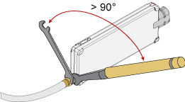
- Position both wrenches within 90 degrees of each other before applying force. Wrenches opposing each other more than 90 degrees will cause a lifting action, which can misalign and damage the connection. The following figures illustrate proper wrench position.
Figure. Correct Wrench Position
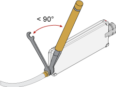
Figure. Incorrect Wrench Position
- Rotate only the connector when you make the connection.
- Hold the torque wrench lightly, at the end of the handle beyond the groove.
Figure. Location of Groove in Handle
- Apply force perpendicular to the wrench handle. This applies torque to the connection through the wrench. Do not hold the wrench so tightly that you push the handle straight down along its length rather than pivoting it, otherwise you apply an unlimited amount of torque.
- Tighten the connection just to the torque wrench "break" point. Refer to the above graphic. Do not tighten the connection further.
You don't have to "fully break" the handle of the torque wrench to reach the specified torque; doing so can cause the handle to kick back and loosen the connection. Any give at all in the handle is sufficient torque.
Do not pivot the wrench handle on your thumb or other fingers, otherwise you will apply an unknown amount of torque to the connection when the wrench does reach its "break" point.
Do not twist the head of the wrench relative to the outer conductor mating plane. If you do, this will apply more than the recommended torque.
Disconnecting the Devices
You will need to use two open-end wrenches to disconnect the 1.85 mm connector from your device under test.
To avoid lateral (bending) force on the connector mating plane surfaces, always support the devices and connections.
- Use an open-end wrench to prevent the device body from turning.
- Use another wrench to loosen the connector nut.
- Complete the disconnection by hand, turning only the connector nut.
- Pull the connectors apart without twisting or bending.
Do not twist one connector out of the other (like removing a light bulb from a socket). Turn the connector nut, not the device body. Major damage to the center conductor of the connector can occur if the device body is twisted.
- Never store connectors loose in a box, in a desk, or in a bench drawer. This is the most common cause of connector damage during storage.
- Keep connectors clean.
- Do not touch mating plane surfaces. Natural skin oils and microscopic particles of dirt are easily transferred to a connector interface and are very diffcult to remove.
- Do not set connectors contact-end down on a hard surface. The plating and the mating plane surfaces can be damaged if the interface comes in contact with any hard surface.
- If a connector or device falls on the floor, inspect thoroughly before using.
- When you are not using a connector, use plastic end caps over the mating plane surfaces to keep them clean and protected.