N1094A/B DCA-M Electrical Oscilloscopes
The N1094A/B DCA-M multiple-channel electrical sampling oscilloscopes are controlled via USB from a PC. The two available models vary in the number of front-panel electrical channel inputs as shown in the following drawings. The N1094A/B option PLK/LOJ oscilloscopes can be used with pattern lock. For installation, safety, and regulatory information, refer to the N109x-series user's guide which can be downloaded from keysight.com.
An N1094A/B with a serial number ≥ MY62100101 requires FlexDCA firmware version A.06.90 or later.
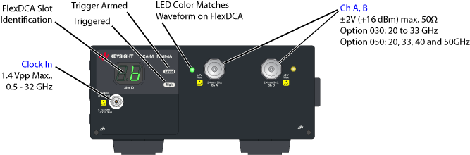
Maximum Clock In non-destruct input voltage is 1.4Vpp. The recommended input is <500 mVp-p.
When four N1094Bs are connected to an N1000A you have a total of 16 electrical channels. And, if four N1045A-04X mini modules are installed into the N1000A, you get a total of 32 electrical channels. All of the 32 channels can be displayed at the same time.
The DCA-Ms are controlled using the same FlexDCA user interface that is used to control the N1000A. As a result, N1000A users will be very familiar with operating the DCA-Ms as well as using remote control. The DCA-Ms use the high-performance elements of both the N1000A oscilloscope acquisition system and the optical channel of the 86105C module. The DCA-Ms can be configured to perform optical transmitter compliance tests.
N1094A Front Panel
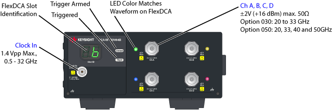
N1094B Front Panel
This module requires FlexDCA firmware version A.05.40 or above.
Key Concepts
- Input signal must meet the following requirements:
- 830 nm to 1600 nm wavelength (multimode or single-mode).
- Symbol rate should be no greater than the selected reference filter. Reference filters are low-pass filters and not bandpass filters. Installed reference filters are listed on the N1092A/B/D's front panel under Filter Rates.
- The Clock In input must meet the following requirements:
- Same symbol rate as the input signal or be a sub-rate clock for proper display of the input signal.
- Triggering occures with any clock between 100 MHz and 32 GHz.
- Trigger setting can be Front Panel or Free Run only.
- Multiple DCA-Ms can be connected to FlexDCA. Delta time values between two channels cannot be compared because each N1094A/B (and DCA-X if connected) uses an independent trigger.
- An DCA-X can simultaineously be connected to FlexDCA.
- Simulated waveforms can be displayed on FlexDCA.
- Use FlexDCA's remote programming commands to configure the N1094A/B.
Aligning waveforms
Because a DCA-M’s acquisition system is independent of the N1000A, the input waveforms may not align after an Auto Scale. This happens if your are using multiple DCA-Ms or a DCA-M with N1000A receiver modules. To align the waveforms:
- Use Rapid Eye to align the channels. Rapid Eye is available on all N1000A and DCA-M scopes. Turn on Rapid Eye and the waveforms will align during an Auto Scale. Rapid Eye is the most convenient way to align the waveforms and maintains very fast throughput. Perform these steps:
- Click Setup > Acquisition to open the Acquisition Setup dialog.
- Select Enable Rapid Eye.
- Select Align Channels During Auto Scale.
- Manually delay the channels. If Rapid Eye is not installed as described above, you can manually add software delay to channels. Although this technique works, acquisition throughput will be reduced. For example, if channels 1A, 2A, and 3A are displayed, add software delay to channels 2A and 3A. The delays are referenced to channel 1A because Auto Scale aligns on the lowest numbered channel that is displayed. To add software delay,
- Click Auto Scale to autoscale the lowest numbered channel.
- For the remaining channels:
- Click Setup > Modules > Channels and select the channel.
- In the Setup dialog, click Advanced for the channel.
- Click Software Delay and enter the desired delay.
Rapid Eye is not available when using math functions or pattern lock.
N1094A/B Front-Panel Indicator Lights
| Indicator | Description |
|---|---|

|
Displays the FlexDCA extended module slot where the DCA-M is installed. The number indicates the channel, which in this picture would be channel 6A. |

|
Green Trigger light indicates that the DCA-M is being triggered. As with the N1000A, this does not indicate that the trigger signal is synchronous with the channel input signal. The trigger must be set to Front Panel and not Module. |

|
Red Trigger light indicates that the clock input signal is missing. |

|
Trigger light off indicates that the DCA-M channel is turned off or if FlexDCA is in single/stop acquisition mode. |

|
Trigger armed light. This light is red if FlexDCA is in single/stop acquisition mode. |

|
Channel indicator light. This light is next to the electrical input connector. When on, the light indicates that the associated FlexDCA channel is turned on and that the waveform is displayed. The light is the same color as the displayed waveform. The Trig'd and Armed indicators do not light unless the channel is turned on. |
Remote programs previously developed using the N1000A FlexDCA interface can be leveraged directly to control an automated N1094A/B system.
Calibrations
The following calibrations are available for the N1092A/B/D within FlexDCA. Each is run from within FlexDCA's Calibration dialog.
- Vertical Calibration
- Allows you to calibrate the N1092A/B/D input channel's vertical response. This calibration is performed without an input signal.
- This calibration is located in the N1094A/B tab on the Calibrations dialog.
- Timebase Calibration
- The N1092A/B/D has its own timebase. If multiple N1092A/B/Ds are used or additional timebases are present, calibrations for each timebase will be listed in the Calibrations dialog. The calibration for each N1092A/B/D is clearly labeled by input channel. Other timebases include 86107A or 86108B-PTD modules.
- This calibration is located in the Timebase tab on the Calibrations dialog.
Options
| Model/Option Number | Description | |
|---|---|---|
| N1094A | Dual electrical channel oscilloscope | |
| N1094B | Quad electrical channel oscilloscope | |
| N1094x-030 | 20 and 30 GHz bandwidth settings | |
| N1094x-050 | 20, 33, 40 and 50 GHz bandwidth settings | |
| N1094x-LOJ | Low jitter timebase | |
| N1094x-STB | Standard timebase | |
| N1094x-PLK | Pattern lock capability | |
| N1094x-FS1 | Fast sampling rate | |
| N1094x-200 | Enhanced jitter analysis software, fixed perpetual license 1 | |
| N1094x-201 | Advanced waveform analysis software, fixed perpetual license | |
| N1094x-300 | Advanced amplitude analysis/Rin/Q-Factor, fixed perpetual license 1 | |
| N1094x-401 | Advanced eye analysis software, fixed perpetual license | |
| N1094x-500 | Productivity package, fixed perpetual license | |
| N1094x-9FP | PAM-N analysis software, fixed perpetual license | |
| N1094x-TFP | IEEE TDECQ analysis, fixed perpetual license | |
| N1094x-PLK | Pattern lock trigger hardware | |
| N1094x-EFP | FlexEye independent channel acquisition and control | |
| N1094x-SIM | InfiniiSim-DCA waveform transformation software, fixed perpetual license | |
| N1094x-C0C | Certificate of calibration | |
| N1094x-UK6 | Commercial calibration certificate with test data | |
| N1094x-1CM | Single instrument rack mount kit | |
| N1094x-1CN | Dual instrument side-by-side rack mount kit |
Requires option PLK.
Available Package Licenses
| Option | Description |
|---|---|
| RND | Research and Development Package license |
| MFG | Manufacturing Package license |