Module Calibration (Slot and Channel)
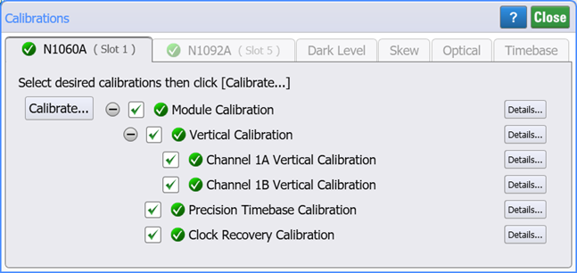
Use the Module tab of the Calibrations dialog to perform the vertical, clock recovery, and precision timebase calibrations on plug-in modules installed in an N1000A DCA-X's module bay as well as DCA-M modules. The Calibrations dialog shows the current status of all available calibrations for a module installed in a particular slot.

Recommended Module Calibration Conditions
A calibration is recommended whenever any of the following conditions are true:
- A DCA-X or DCA-M power has been cycled
- A DCA-X module has been removed and then reinserted since the last calibration
- The temperature change of a DCA-X or DCA-M exceeds 5°C compared to the temperature of the last module calibration ( ΔT > 5°C)
- Time since the last calibration has exceeded 10 hours
Always remove or disable all inputs to the module. However, inputs do not have to be removed from 83496A modules.
The vertical calibration uses known signal levels in the DCA-X. Introducing an outside signal source will interfere with the calibration factors and decrease the accuracy of the calibration.
Re-seating the module into the DCA-X may affect the electrical connections, which in turn affects the data sampling process.
Vertical Calibration
A vertical calibration for an input channel enhances measurement precision by establishing calibration factors which compensate for imperfections in the measurement system, such as variations due to the ambient temperature. Although it is recommended that you routinely perform this calibration for best measurement accuracy, it is not required. The plug-in module amplitude accuracy specifications apply when the module calibration is valid. Module calibration factors are valid only for the mainframe and slot in which the module was calibrated. Vertical calibrations do not require any external equipment setup. Always remove or disable all inputs to the module.
Each dialog tab lists its calibrations along with the status icons that are shown in the following table.
| Icon | Description |
|---|---|
|
|
Calibration is selected |
|
|
Calibration is unselected |
|
|
Calibrations are partially selected |
|
|
Calibration is current |
|
|
Calibration is recommended |
|
|
Calibration has never been performed |
 Click Calibrate to start all selected calibrations. To select the desired calibrations, select or clear the selection icons. (These icons are defined in this topic's sidebar.)
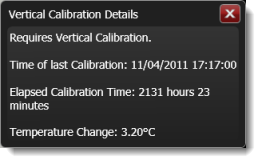
Click Details to view information such as the time and temperature at which the last calibration was performed.

Precision Timebase Calibration
A precision timebase calibration is available for 86107A and 86108A/B modules. The timebase calibration measures a reference clock signal and saves calibration factors to compensate for errors in the measurement system such as variations due to ambient temperature. The calibration results in the best measurement precision. No signal or connections are required for the calibration.
To perform a timebase calibration on N109x-series DCA-M modules, N1000A DCA-X with option PTB, click on the Timebase tab.
Clock Recovery Calibration
A clock recovery calibration is available for the following modules:
- N1060A and 86108A/B precision waveform analyzer modules.
- N1092A/B option CDR DCA-M.
- N107x-series DCA-M.
- 83496A/B clock recovery modules.
A module calibration ensures that the proper module calibration factors are generated to compensate for errors in the measurement system. The calibration results in the best instrument precision.
To Verify Electrical-Channel Calibration Accuracy
- Configure the DC voltage level for the DCA-X's front-panel Cal Out.
- Connect the Cal Out to the channel input and measure the signal level.