7. Waveform Acquisition & Display
In this topic you'll learn about the relationship between sampled waveforms, their display, and exported waveform files in Eye and Oscilloscope modes. Within FlexDCA, waveforms are stored as either Single-Valued (SV) or Multi-Valued (MV) data, depending on mode and settings. Oscilloscope and TDR modes are designed to work with SV waveforms. Eye and Jitter modes are designed to work with MV waveforms.
| Single-Valued PAM4 Waveform (Oscilloscope Mode) |
Multi-Valued PAM4 Waveform (Eye Mode) |
|---|---|
|
|
SV waveforms are waveforms in which each data point's time position has one and only one amplitude value. SV waveforms are stored in consecutive memory known as a waveform record. FlexDCA automatically determines the waveform record's length. If needed, you can manually set the length in the Acquisition Setup dialog. For pattern-locked bit streams, the waveform record length is determined by the following equation:

MV waveforms are waveforms in which each data point's time position in a symbol can have multiple amplitude values. Multiple SV waveform acqusitions are combined to produce a MV waveform. This is accomplished by transferring each acquisition's waveform record immediately to a color-grade gray-scale (CGS) database. The CGS database is a 751 by 521 two-dimensional histogram where multiple "hits" on a single data point are counted to construct a histogram. Statistical-based measurements are performed on this histogram. Either of the two following methods are used to combine SV waveforms in the CGS database:
- Symbols regardless of boolean state or position are "wrapped" by unit interval on top of each other to produce an eye diagram, or
- A range of identical symbols from a pattern are superimposed on the database to produce a MV bit stream. This requires pattern lock or a pattern trigger.
Oscilloscope Mode
In Oscilloscope mode, all waveforms are SV. Pattern locking (also known as pattern trigger) enables an entire pattern to be viewed. Additional waveform acquisitions replace the previous waveform record.
In Oscilloscope mode, a random PRBS signal can appear to be an MV waveform (like an eye diagram) even though the data is not stored in a database. Oscilloscope mode measurements cannot be made on these waveforms. To properly view such a signal in Oscilloscope mode, turn pattern lock on (requires N1000A Option PLK) or use a pattern trigger.
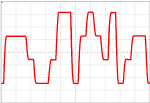
| Pattern Lock On (measurements are valid) |
Pattern Lock Off (measurements cannot be made) |
|---|---|

|
|
Without Pattern Lock
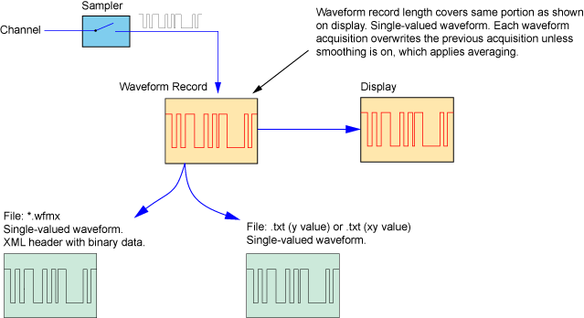
Waveform smoothing cannot be applied. The acquired waveform can be exported to the following waveform file types. The portion of the waveform that is saved in each file type is identical to the waveform in the waveform record and shown on the display.
- Internal format file (.wfmx). The internal format file has an XML header that describes scaling information followed by binary data. If this file format is imported into FlexDCA's waveform memory, you must use the Waveform Memories dialog to scale the X-axis data.
- Y-values text file (.txt). This file type can be imported into FlexDCA's waveform memory.
- XY-values text file (.txt). This file type can be imported into FlexDCA's waveform memory.
The following figure shows the relationship between FlexDCA's waveform record, the displayed data, and the available exported file types.
Pattern Locked
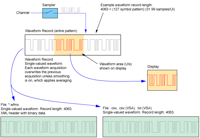
If waveform smoothing is applied, the data is mathmatically combined (average or median). There is one X value for each data sample. The acquired waveform can be exported to the following waveform file types. The contents of each of these file types include the data from the entire pattern waveform regardless of the time span that is shown on the display.
- Internal format file (.wfmx). The internal format file has an XML header that describes scaling information followed by binary data. If this file format is imported into FlexDCA's waveform memory, you must use the Waveform Memories dialog to scale the X-axis data.
- Comma-Separated Values (CSV) text file (.csv). If this file format is imported into FlexDCA's waveform memory, you must use the Waveform Memories dialog to scale the X-axis data.
- VSA recording CSV text file (.csv). This file type cannot be imported into FlexDCA's waveform memory.
- VSA recording tab-delimited text file (.txt). This file type cannot be imported into FlexDCA's waveform memory.
The following figure shows the relationship between FlexDCA's waveform record, the displayed data, and the available exported file types.
Eye Mode (without Pattern Lock)
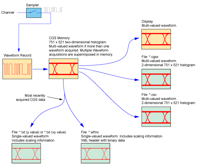
In Eye/Mask mode, without pattern lock, an eye diagram is viewed for random waveforms. Symbols regardless of boolean state or position are "wrapped" by unit interval on top of each other to produce an eye diagram. The acquired waveform can be saved to the following file types:
- CGS database file (.cgsx). The CGS file is the composite of all waveform data that is shown on FlexDCA's display. This file can be imported into FlexDCA's CGS memory.
- Internal format waveform (.wfmx) file. The internal format file contain the CGS data for the most recent acquisition. The file contains SV data as multiple acquisitions have not been superimposed on the database. The data starts with the left-most X-axis point and progresses to the right-most X-axis point in the database. Data points are not associated with other data points in bit trajectories. The internal format file has an XML header with scaling information followed by binary data. This file can be imported into FlexDCA's waveform memory.
- Y-values text file (.txt). The Y-values format file contain the CGS data for the most recent acquisition. The file contains SV data as multiple acquisitions have not been superimposed on the database. The data starts with the left-most X-axis point and progresses to the right-most X-axis point in the database. Data points are not associated with other data points in bit trajectories. The internal format file has an XML header with scaling information followed by binary data. This file can be imported into FlexDCA's waveform memory. This file can be imported into FlexDCA's waveform memory.
- XY-values text file (.txt). The XY-values format file contains the CGS data for the most recent acquisition. The file contains SV data as multiple acquisitions have not been superimposed on the database. The data starts with the left-most X-axis point and progresses to the right-most X-axis point in the database. Data points are not associated with other data points in bit trajectories. The internal format file has an XML header with scaling information followed by binary data. This file can be imported into FlexDCA's waveform memory.
The following figure shows the relationship between FlexDCA's waveform record, the displayed data, and the available exported file types.
Eye Mode (Pattern Locked)
In Eye/Mask mode, a bit stream or eye diagram is viewed depending on the settings that are located in the Acquisition Setup dialog and shown in the following table. Bit streams in Eye mode are multi-valued from the CGS database. Waveform smoothing can be applied when pattern lock is used.
| Pattern Lock Settings | ||||
|---|---|---|---|---|
| Off | Acquire Entire Pattern Off |
Acquire Entire Pattern On |
||
| Wrap Waveform Setting |
On | eye diagram | bit stream | eye diagram |
| Off | bit stream | |||
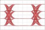
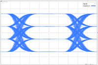
| Bit Streams Appear Single-Valued | Traditional Eye Diagram |
|---|---|
|
|
|
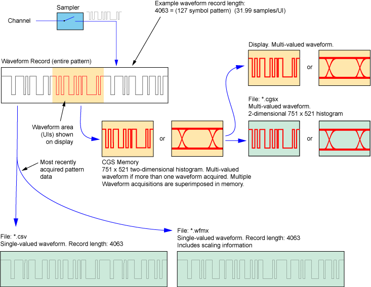
In Eye mode, turning pattern lock on uses pattern triggering to capture data for all of the symbols in the pattern. (Acquire Entire Pattern is turned on by default.) Data for the entire 127-symbol pattern have been overlaid in the two-dimensional histogram. After the first pattern acquisition, there is one X value for each data sample. As additional patterns are acquired, multiple Y values will exist. The waveform record length for the waveform is the number of symbols in the pattern multiplied by the number of samples taken per Unit Interval (UI). In this case, 4063 record points.
The acquired waveform can be saved to the following file types:
- CGS database file (.cgsx). The CGS file is the composite of all waveform data that is shown on FlexDCA's display. The file only includes data for the portion of the pattern that is shown on the display.
- Comma-Separated Values (CSV) waveform text file (.csv). The CSV file contain all of the data for the most recent pattern acquisition which includes data for the entire pattern. There is no scaling information in the CSV file.
- Internal format waveform (.wfmx) file. The internal format file contains all of the data for the most recent pattern acquisition which includes data for the entire pattern. The internal format file has an XML header with scaling information followed by binary data.
The following figure shows the relationship between FlexDCA's waveform record, the displayed data, and the available exported file types.
TDR Mode
In TDR mode, it's important to understand how waveform data is saved into exported files. We'll consider the following three file types:
- Internal format file (.wfmx). The internal format file has a
- Y-values text file (.txt). This file type can be imported into FlexDCA's waveform memory.
- XY-values text file (.txt). This file type can be imported into FlexDCA's waveform memory.
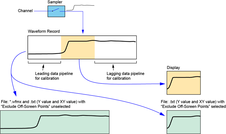
In TDR Mode, waveforms that are acquired when TDR step hardware is active, and have a TDR calibration enabled, require additional waveform points beyond what is displayed on screen. These leading and lagging pipeline points are used to apply the TDR calibration effects to the sampled waveform. By default, the leading and lagging data points are saved to any waveform file that you create. Sometimes the extra pipeline data saved in waveform files can add complexity to post-processing of waveform data. Starting with FlexDCA revision A.07.80, an Exclude Off-Screen Points setting prevents any off-screen data points from being saved in waveform files. This concept is shown in the following figure. The Exclude Off-Screen Points setting is located in the File Save dialog’s Waveform tab.