6. Understanding Signal Parameters
This topic describes the NRZ, PAM4, and PAM8 modulation formats and using clocks as an input waveform. The topic also describes how these waveforms relate to Baud rate and bit rate. You'll also learn how these values are represented within FlexDCA's dialog settings.
NRZ, PAM4, and PAM8 Symbols
The smallest unit of digital information is a bit: 0 or 1. Before transferring bits, digital information must be encoded into physical entities. For NRZ and PAM coding, information (bit values) are indicated by changes in amplitude (voltage levels). A voltage level, known as a symbol, identifies the value of one or more bits. The following table presents how bits and symbols are related in the different modulation schemes.
| Properties | Format | ||
|---|---|---|---|
| NRZ | PAM4 | PAM8 | |
| Number of Symbols Transmitted Per Byte | 8 | 4 | 3 |
| Number of Bits Packed into a Symbol | 1 | 2 | 3 |
| Example Byte's Transmitted Symbol Levels | 01110011 | 1303 | 346 |
| Number of Voltage Levels Used | 2 | 4 | 8 |
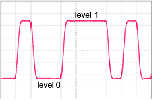
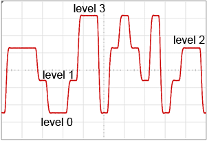
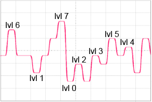
An NRZ symbol can be a zero (low) or one (high). A PAM4 symbol can be a 0, 1, 2, or 3 representing 2 bits. A PAM8 symbol can be a 0, 1, 2, 3, 4, 5, 6, or 7 representing 3 bits.
The following figures identify the different available symbols (levels) transmitted for the different waveforms.
Definitions
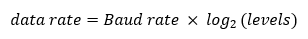
Bit Rate (Data Rate)
The terms Bit rate and Data Rate are the same rate; they are the rate at which bits are transmitted in bits-per-second. For PAM4 and PAM8 it counts the bits packed into a symbol. Because a symbol includes multiple bits, PAM4 and PAM8 have higher data rates. This is expressed by the following equation, where levels equals the number of voltage levels in the coding scheme:
For example, the data rate for PAM4 transmitted at a 10 GBd:
20 GBd = 10 GBd x 2
Baud Rate (Symbol Rate)
Baud rate, also known as symbol rate, is the number of symbols (level changes) transmitted per second. PAM symbols contain more information than the NRZ symbols. The data rate is related to Baud rate:
- For NRZ, the data rate is equal to the Baud rate, because no bits are packed into symbols.
- For PAM4, data rate is double the Baud rate. This is because PAM4 codes 2 bits into each symbol, so PAM4's data rate is twice its Baud rate.
- For PAM8, data rate is atriple the Baud rate. This is because PAM8 codes 3 bits into each symbol, so PAM8's data rate is three times its baud rate.
Unit Interval
Unit Interval (UI) is the nominal time to transmit one symbol:
| Property | NRZ | PAM4 | PAM8 |
|---|---|---|---|
| Baud Rate | 10 GBd | 10 GBd | 10 GBd |
| Data Rate | 10 Gb/s | 20 Gb/s | 30 Gb/s |
| Unit Interval | 100 ps | 100 ps | 100 ps |
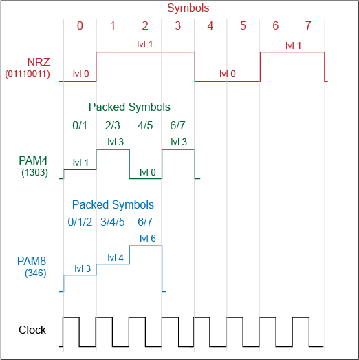
Packing Bits into Symbols
The following paragraphs illustrate how code packing of multiple bits is accomplished. More complex versions of these coding schemes exist, but for conveying the basic concepts of bit packing this explanation simple coding schemes will be presented. For each format, we'll use the example byte (01110011) which represents an ASCII lower-case letter "s" (decimal 115). The following figure illustrates the three waveforms for an ASCII "s". To save space, the vertical scale has been reduced for the PAM waveforms. The time scale clearly shows that the PAM waveforms take fewer symbols and therefor less time to transmit the same information when compared to the NRZ waveform.
NRZ Coding
The ASCII code for the letter "s" is binary 01110011. Since NRZ coding only has two amplitude levels (0 and 1), this symbol would simply be transmitted as these as the bits (symbols) in this byte:
01110011
NRZ uses one bit per symbol, and the Baud rate happens to be the same number as the data symbol rates.
PAM4 Coding
PAM4 coding has four amplitude levels: 0, 1, 2, and 3. To represent the letter "s" in PAM4:
- Split the byte (01110011) into four groups of two bit symbols:
- Symbol 0:
01. - Symbol 1:
11. - Symbol 2:
00. - Symbol 3:
11. - Convert the binary values in each of the four symbols into their decimal equivalent. These decimal equivalents will represent PAM4 amplitude levels:
1,3,0, and3.
Notice that NRZ must transmit 8 symbols to represent the letter "s" whereas PAM4 only requires 4 symbols to send the same 8 bits. Consider what happens if the NRZ and equivalent PAM4 bits were both transmitted at the same 10 Gb/s (bits/second) rate. In the time that NRZ's first symbol to be transmitted, PAM4 transmits two bits (one symbol) which is equivalent to two NRZ symbols. In other words, while NRZ's bit rate (also known as symbol rate) is 10 GB/s, PAM4's bit rate is 20 Gb/s double that of NRZ.
For example, a 25.78 GBaud PAM4 signal transmits 51.56 Gb/s. Each unit interval is 38.79 ps long and the nominal amplitude in the center is exactly one out of 4 possible choices. Some RF signals use complex modulations such as QAM-16. In this case each symbol contains one out of 16 possible complex values and the symbol rate is four times the baud rate.
| PAM4 Level | Decimal Value | Binary Value |
|---|---|---|
| 3 | 3 | 11 |
| 2 | 2 | 10 |
| 1 | 1 | 01 |
| 0 | 0 | 00 |
PAM8 Coding
PAM8 coding has eight amplitude levels: 0, 1, 2, 3, 4, 5, 6, and 7. To represent the letter "s" in PAM8:
- Split the byte (01110011) into three groups of three bit symbols:
- Symbol 0:
011. - Symbol 1:
100. - Symbol 2:
110. - Convert each of the three groups into their decimal equivalent that represent PAM8 amplitude levels:
3,4, and6.
For PAM8, a coding rule requires that a padding 0 bit be added the last group. This is shown in red in the above example.
Notice that NRZ requires transmitting 8 symbols to represent the letter "s" where PAM4 only requires 4 symbols. Consider what happens if the NRZ and equivalent PAM4 bits were both transmitted at the same 10 GBd (symbols/second) rate. In the time that NRZ transmits its first bit of eight bits, PAM4 transmits its first symbol which is equivalent to two NRZ bits. In other words, while NRZ's data rate is 10 Gb/s, PAM4's data rate is 20 Gb/s double that of NRZ.
| PAM8 Level | Decimal Value | Binary Value |
|---|---|---|
| 7 | 7 | 111 |
| 6 | 6 | 110 |
| 5 | 5 | 101 |
| 4 | 4 | 100 |
| 3 | 3 | 011 |
| 2 | 2 | 010 |
| 1 | 1 | 001 |
| 0 | 0 | 000 |
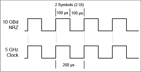
Clock Input Waveform
At times, you may want to perform measurements on a clock signal. For example, using FlexDCA's Jitter Mode to measure clock jitter. In this case, FlexDCA can interpret the input waveform's rate as a clock (square wave) or as an NRZ waveform (alternating pattern of zeros and ones). The following figure illustrates the two interpretations of a 5 GHz clock as either 5 GHz or 10 GBd.
Be aware that FlexDCA's dialogs will show this same input waveform using 5 GHz and 10 GBd depending on the setting. For example, in Jitter Mode here are the values that are displayed for the following settings:
- Jitter Panel's Src Rate: 5 GHz.
- Trigger Setup dialog (Pattern Lock Setup tab) Symbol Rate: 5 GBd
- Instead of 5 GBd, one would expect this value to be 10 GBd or 5 GHz. Internally, FlexDCA properly applies this setting internally as 5 GHz.
In this situation if you want the proper values displayed, in the Trigger Setup dialog (Pattern Lock Setup tab):
- Clear the Symbol Rate's Auto Detect and enter 10 GBd.
- Clear the Clock Divide Ratio's Auto Detect and select a 1:2 (Sub-Rate).
- Clear the Signal Type (Jitter Mode)'s Auto Detect and select Data.