4. ESD and TDR Modules
The input circuits of the N1055A, 54754A, and 54753A TDR/TDT plug-in modules can be damaged by ESD. Avoid applying static discharges to the front-panel input connectors. Frequency, a static charge potential will build up between the connecting cable's center conductor and the shield. Observe the following best practices:
- Avoid touching the front-panel input connectors without first touching the instrument's frame.
- Before connecting any coaxial cable to the connectors, momentarily short the center and outer conductors of the cable together.
- Be sure the instrument is properly earth-grounded to prevent buildup of static charge.
- On 54754A modules, use the ESD gate as described in this topic.
- On 1055A TDR modules, which do not have an ESD gate, discharge the cable to a suitable metal area of the input connector.
Improper connector care, cleaning, or use of mismatched cable connectors can invalidate the published specifications and damage connectors. Clean all cables before applying to any connector. Repair of damaged connectors due to improper use is not covered under warranty.
The input connectors are very sensitive to electrostatic discharge (ESD). When you connect a device or cable that is not fully discharged to these input connectors, you risk damage to the module and expensive instrument repairs.
Electrostatic discharge (ESD) can damage the input circuits of the N1055A, 54754A, and 54753A TDR/TDT plug-in modules. Avoid applying static discharges to the front-panel input connectors. Before connecting any coaxial cable to the connectors, momentarily short the center and outer conductors of the cable together. Avoid touching the front-panel input connectors without first touching the frame of the instrument. Be sure the instrument is properly earth-grounded to prevent buildup of static charge.
Protecting TDR/TDT Modules that have 3.5 mm Input Connectors
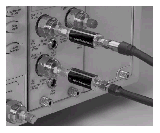
 For additional protection, use an Keysight N9355CK01 DC coupled limiter (DC to 26.5 GHz) as shown in this picture. It is used to protect sensitive oscilloscope channels from damage due to electric overload stress (EOS) and electrostatic discharge (ESD). For example, voltages in excess of ±2V can damage high-performance samplers used in oscilloscopes. The limiter dramatically reduces the likelihood that such voltages will reach the sensitive part of the instrument, ensuring that the oscilloscope will perform reliably. Instruments with dual electrical channels, such as the 54754A, will require two N9355CK01 limiters. Step generators within the TDR modules use
≤0.2V, which is less than the diode threshold of the N9355CK01 limiter. The N9355CK01 can also be used to protect the electrical channel of the 86105x and similar modules, as long as the signal does not exceed –0.5V to +0.5V. The N9355CK01's voltage drop is ±0.6V to 0.7V at ±10 mADC.
The N9355CK01 will protect instruments from occasional and short voltage spikes. A major power source, such as a high voltage and current supply can still cause severe damage to the limiter itself, or the instruments. Operators should continue using industry standard EOS and ESD practices to minimize this risk.
Static-Safe Workstation
- All measurements should be performed at a Static-Safe Workstation.
Using the ESD Gate
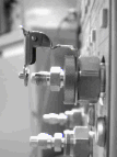
- Use ESD accessories to make your workstation static-safe. Make sure the ESD gate is installed as shown in the following graphic.

- Connect a test cable to the device you are testing.
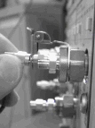
- On the other end of the test cable, short the cable's center conductor and shield to the ground contact on the ESD gate, as shown in the following graphic.

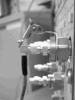
- Lift the ESD gate out of the way and connect the test cable, as shown in the following graphic.
