5. Use a Torque Wrench
The information in this topic shows the proper techniques to use when making a connection with a torque wrench. The examples are for 1 mm connectors but the same techniques also apply to other connector types. Using a torque wrench will protect your oscilloscope's front-panel connectors as well as devices such as adapters, cables, and pickoffs.
Failure to follow the guidelines for proper connector handling and avoiding electrostatic discharge (ESD) can result in severe damage to the product. In some cases, an input connector is an integral part of an internal electrical sampler so always use improper cleaning, connecting, and handling techniques.
For 1.0 mm connectors, the maximum torque setting is 4 in-lb (0.45 Nm).
For 2.92 mm connectors the maximum torque setting is 8 in-lb (0.9 Nm). 2.92 mm connectors are used on N1000A's Trigger and Precision Timebase Inputs and on an N1060A module’s Precision Timebase and Recovered Clock connectors.
Precision 3.5 mm Microwave connectors are compatible with an SMA connector within its specification. Due to the variable quality of the SMA connector, mating with an SMA can sometimes cause severe damage to the 3.5 mm connector.
Channel Input Connectors
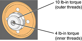
On several DCA-X modules and DCA-M modules, a front-panel 1 mm Channel Input connector is used as shown in this picture. These 1 mm connectors have both outer in inner threads that require different torque specifications. Always use the correct torque specification as noted when making connection to the Channel Input. Damage to the Channel Input connector results in an expensive repair and extended down time while the module is being repaired.
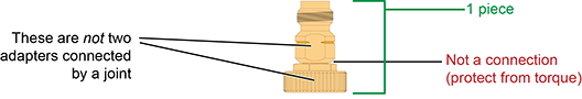
Channel Input Y1901/3B Adapters
The following picture show the two types of ruggedized 1mm adapters, which are supplied in the N1030A and N1060A accessory kits:
- 1 mm to 1.85 mm Y1901B adapter
- 1 mm to 2.92 mm Y1903B adapter
These adapters are designed to be installed on the front-panel channel inputs. It is recommended that you always use them. Due to the physical requirements needed to obtain high performance, the geometry of these, as well as all, 1 mm connectors, demands special care to avoid expensive damage as explained in this document.
Although not supplied in the kit, a 1 mm-to-1 mm Y1900B adapter is available to purchase from Keysight Technologies.
Making RF Connections
- Work at a static-safe workstation.
- Visually inspect the connectors. If necessary, clean the connectors. Carefully align the connectors. The male connector center pin must slip concentrically into the contact fingers of the female connector.
- Push the connectors straight together.
- Tighten lightly using only your fingers as, at this point, all you want is a connection in which the outer conductors make gentle contact at all points on both mating surfaces. Very light finger pressure (no more than 2 pound-inches of torque) is enough.
Do not twist one connector into the other (like inserting a light bulb). This happens if you turn the device body rather than the connector nut. Major damage to the center conductor can occur if the device body is twisted.
- Use a torque wrench to make the final connection. This guarantees perfectly tight, consistent connections that prevents connector damage. Refer to Applying Torque for the proper handling of the wrenches and to view the correct connector “flats” on which to position the wrenches.
The maximum torque setting is 4 in-lb (0.45 Nm) for 1.0 mm connectors.
Rotate only the connector nut when you make the connection. Do not rotate the cable or adapter.
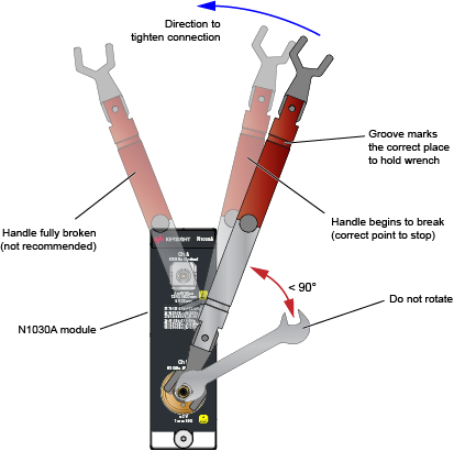
Hold the torque wrench lightly at the groove located at the end of the handle.
Apply force perpendicular to the wrench handle. This applies torque to the connection through the wrench. Do not hold the wrench so tightly that you push the handle straight down along its length rather than pivoting it, otherwise you apply an unlimited amount of torque.
Tighten the connection just to the torque wrench "break" point as shown in Wrenches Positioned on Correct Flats. Do not tighten the connection further.
Applying Torque
For the 1 mm Channel Input connector, use the dual torque wrench shown in the Wrenches on Channel Input.
The silver end of the dual torque wrench is 4 lb-in. The red end of the torque wrench is 10 lb-in.
Selecting and Positioning the Wrenches
The following figures show the proper “flats” on which to place the wrenches for several possible connections.
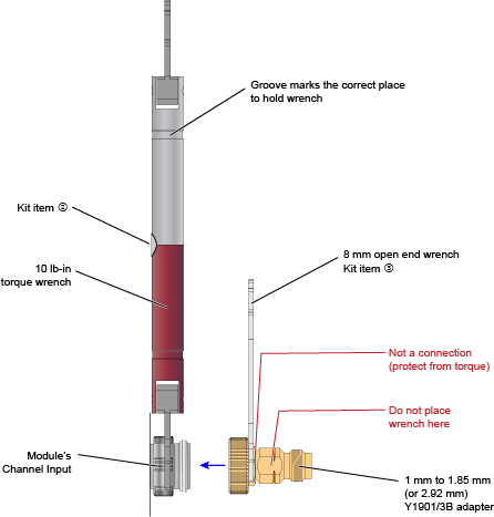
Y1901/3B Adapter to Channel Input
This figure show the correct placement of the 10 lb-in dual torque wrench (the red end) and the 8 mm open end wrench. On the Y1901/3B adapter, connect the 8 mm wrench on the flats that are adjacent to the knurled ring as shown in this figure.
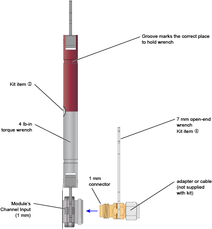
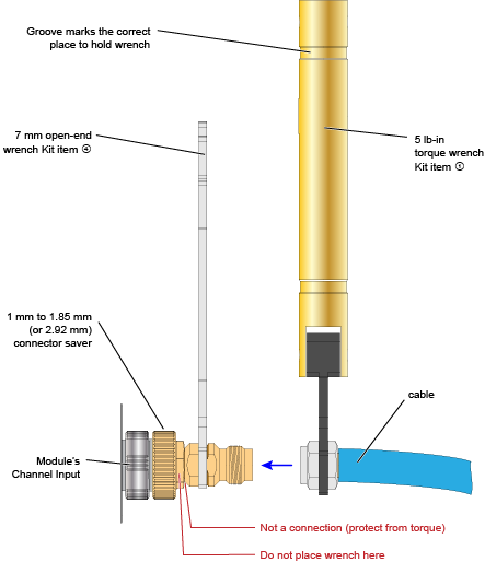
Cable or Adapter to Y1901/3B Adapter
This figure show the correct placement of the 5 lb-in torque wrench and the 7 mm open end wrench for connecting a cable, adapter, or other item to the Y1901/3B adapter.
Adapter to Channel Input (without Y1901/3B)
It is recommended that you always connect an Y1901/3B adapter to the 1mm channel input. However, if you want to connect an adapter or cable directly to a channel input connector, use the 4 lb-in end of the dual torque wrench (silver end of the dual torque wrench). Do not use the red end of the dual torque wrench which is only used when connecting the stronger outside channel-input connector threads to the Y1901/3B connector.
Never apply in excess of 4 lb-in of torque to the 1mm channel input’s inner threads. Confirm also that your adapter or channel connector can withstand 4 lb-in.