CNRZ5 Operator

 The CNRZ5 Decode (Chord NRZ 5 bit) operator decodes a CNRZ5 coded signal. It is one of two chord operators. The operator takes the six encoded input signals (representing five bits of information) and outputs five decoded NRZ waveforms with each output representing one of the five output bits. With five bits/symbol, the shortest pattern length to show all possible bit combinations is 32 symbols long (25 symbols).
To ensure proper decoding, the input waveforms must be aligned.
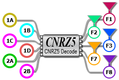
After placing the operator in the construction area, drag the six input channels or memory waveform inputs from the left-side panel onto the operator's left-side inputs. Drag right-side function colors to the operator's right-side outputs. If your input waveforms are in files, first load each waveform file into either a waveform memory (preferred method) or a simulated module's channel. If you import them into a simulated module, you must specify the waveform's amplitude in the simulated module's Setup dialog.
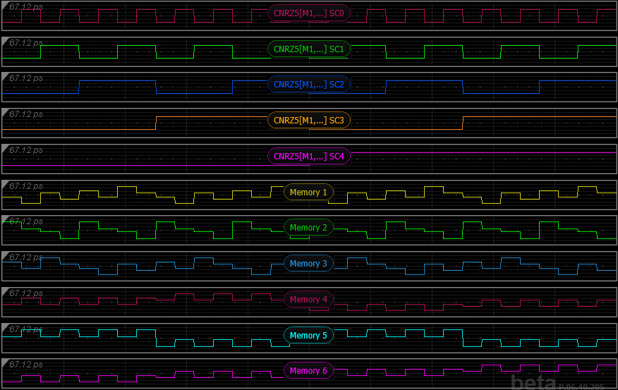
The following picture shows all of the CNRZ5 waveforms displayed in FlexDCA's Oscilloscope mode. All possible bit combinations are shown. The amplitude of the input signals are not equal. The encoding has different amplitude inputs (wires 1 and 4 are smaller) to yield equal amplitude outputs.
| Connection | Description | Idealized Waveform on Each Input/Output |
|---|---|---|
| Inputs | Six CNRZ5 encoded channels (or memories) which together represent one CNRZ5 coded signal:
|
Wire 0: 
Wire 1: 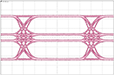
Wire 2: 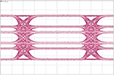
Wire 3: 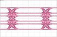
Wire 4: 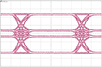
Wire 5: 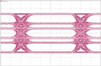
|
| Outputs | Five decoded waveforms (Sub-Channels) each in NRZ format where each waveform represents a bit:
|
NRZ: 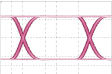
|
Configuring the Operator
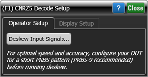
After connecting the operator's inputs to channels or memories and the operator's outputs to displayed waveforms, click on the operator to open the CNRZ5 Decode Setup dialog. The dialog's Operator Setup tab allows you to deskew the input signals which, for each channel, includes the full function chain leading up to the operator. Deskew works with channel inputs but not waveform memory inputs. For optimal speed and accuracy, configure the DUT for a short PRBS pattern before running deskew. A PRBS-9 pattern is recommended.
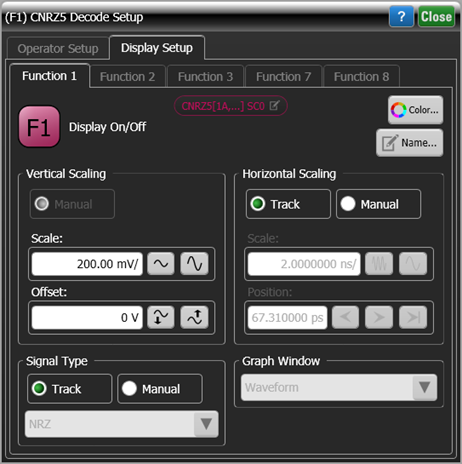
 Use the dialog's Display Setup tab to turn the display of the output waveforms on or off and to configure its vertical scaling, horizontal scaling, signal type, and graph window. In the dialog and on the displayed waveform, notice that the output waveform's name includes the term "SC" which stands for Sub Channel. The name also includes the function output port's number.