Sources of Measurement Error
The three primary sources of error in TDR/TDT measurements are cables and connectors, the instrument, and the step generator.
Cables and Connectors as an Error Source
The cables and connectors located between the TDR step source, the Device Under Test (DUT), and the instrument can significantly affect measurement results. Impedance mismatches and imperfect connectors add reflections to the actual signal being measured. These factors can distort the signal and make it difficult to determine which reflections are from the DUT and which are introduced from other sources.
In addition, cables are imperfect conductors that become more imperfect as frequency increases. Cable losses, which increase at higher frequencies, increase the rise time of edges and cause the edges to droop as they approach their final value.
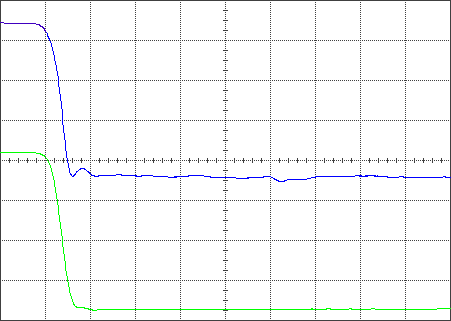
The following picture depicts how cables and connectors affect measurements. The upper waveform is the reflection of a step from a short circuit. Connections cause the reflections at the peak of the step and along the baseline. Cable loss yields the rounded transition of the step to its baseline level. The lower waveform illustrates the measured data after being corrected with a TDR calibration.

The Instrument as an Error Source
An instrument can introduce errors into measurements in several ways. The finite bandwidth of an instrument translates to limited rise time. Edges with rise times that approach the minimum rise time of the instrument are measured slower than they actually are. When measuring how a device responds to a very fast edge, the instrument's limited rise time may distort or hide some of the device response.
The instrument can also introduce small errors that are due to the trigger coupling into the channels and channel cross talk. These errors appear as ringing and other non-flatness in the display of the measurement channel baseline and are superimposed on the measured waveform. They are generally small and are only significant when measuring small signals in balanced test fixtures.
The Step Generator as an Error Source
The shape of the TDR step stimulus is also important for accurate measurements. The device under test responds not only to the step, but also to the aberrations on the step such as overshoot and non-flatness. If the overshoot is substantial, the response of the device under test can be more difficult to interpret.
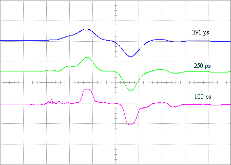
The rise time of the step is also extremely important. The rise time in the N1000A is adjustable through the Setup Wizard. To determine how the device under test will actually respond in its intended application, you should test it at edge speeds similar to those it will actually encounter. Consider the example of a BNC connector in the following picture.

Only about 3% of a 391 ps rise time edge (top waveform) is reflected by a BNC connector whereas 6% of a 250 ps rise time edge (middle waveform) is reflected and about 8% of a 100 ps rise time edge (bottom waveform) is reflected.
In the above measurement scenario, the results obtained using a 100 ps rise time step stimulus do not apply for a connector that recognizes edges that are always slower than 350 ps. The connector might be acceptable for 350 ps edges but not for 100 ps edges. Measurements made at inappropriate rise times can yield invalid conclusions.
Edge speed is also critical when using TDR to locate the source of a discontinuity along a transmission line. Just as the limited rise time of the instrument can limit the accuracy of this kind of measurement, the rise time of the step source can also limit accuracy.
The edge speed also affects the spatial resolution of a TDR measurement or its ability to resolve discontinuities along a transmission line. This can be important when trying to extract models for an interconnect.
The rise time of the measurement system is limited by the combined rise times of the oscilloscope and the step generator. It can be approximated by the following equation:

In a system with zero minimum rise time, the response of a discontinuity would not be attenuated at all. A real system has a limited rise time, which acts as a low-pass filter. If the step stimulus used is too slow, the true nature of the discontinuity may be disguised or may not even be visible. The cause may be more difficult to physically locate. Notice in the previous figure that as the rise time of the step stimulus is decreased, the true nature of the reflection from the device under test becomes more apparent.