T and S Parameters
This topic describes the use of T-parameters (time-domain parameters) and S-parameters (scattering parameters) to identify Time Domain Reflectometry (TDR) and Time Domain Transmission (TDT) waveforms. During measurements, an N1055A TDR module sends stimulus steps to the DUT and captures TDR and TDT response waveforms. These traditional TDR/TDT waveforms are time domain parameters waveforms that display the relationship between stimulus and response waveforms (voltage-ratio). This provides an intuitive view of a DUT's impedance profile (reflection and transmission characteristics) versus distance.
If the N1010200A Manufacturing (L-MFG) or N1010300A Signal Integrity (L-SNT) license installed, time domain parameter waveforms can be transformed to the frequency domain as S-parameters, which are power-ratio measurements that include magnitude and phase. S-parameters describe how a test device modifies a signal. Typical S-parameter measurements include return loss, insertion loss, near-end cross talk (NEXT), and far-end cross talk (FEXT).
Measurement Names
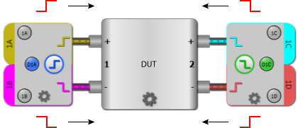
The identification scheme used for S-parameters is also used to identify time domain parameter waveforms. The signal input to a device is referred to as the stimulus and the signal received from the device is referred to as the response. Measurements names begin with the capital letter "T" for time domain parameters and "S" for S-parameters. The letter is followed by numbers that represent the ratio of the signals on the device's input and output ports. For example, the T21 time domain parameter describes an insertion loss measurement made with the stimulus applied on Port 1 and the response on Port 2, as shown in the following figure. The output port's number is listed first followed by the input port's number. In normal usage, the ratio notation 2:1 is shortened to 21. The following picture shows how a T21 / S21 test setup would be represented in FlexDCA's DUT layout panel in the TDR Setup dialog.
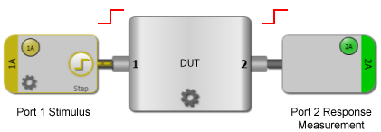
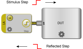
In a single-ended device, one transmission line carries data to a port which is comprised of one terminal. On a single-ended device with one port, only the return-loss (reflection) measurement T11 (and corresponding S11 in the frequency domain) is available. On single-ended devices with two ports, measurements T11, T21, T12, and T22 are available with associated S11, S21, S12, and S22 measurements.
Balanced Devices
In a balanced device, two transmission lines carry complementary data to a single port which is comprised of two terminals. The two lines can be driven with either a differential (anti-phase) or common (in-phase) stimulus. The advantage of using a balanced device is that a receiver can reject a signal that is common to both conductors. Also, radiation is reduced due to cancellation of electromagnetic fields.

Balanced devices can also be measured during mixed stimulus use, where the input and output stimulus types are different. For example, the input port could be driven differentially while the common response is measured. The S-parameters measure the impedance between the two lines. Time-domain parameter and S-parameter names for balanced ports include two additional letters: C (common) and D (differential):
- SCCxx (common measurement, where xx represents port numbers)
- SDDxx (differential measurement)
- SDCxx (mixed-stimulus measurement: common input, differential output)
- SCDxx (mixed-stimulus measurement: differential input, common output)
As with the port numbers, the convention is to list the letter (C or D) representing the output port stimulus type first followed by the letter representing the stimulus type of the input port.
2-Port Single-Ended Measurements
The following table lists all four possible combinations of time domain parameter and S-parameter measurements on a two-port device. To find the measurement, locate the intersection of the stimulus (input) port column and the response (output) port row. The return loss measurements are S11 (forward) and S22 (reverse). The insertion loss measurements are S21 (forward) and S12 (reverse).

| Time Domain Parameters | S-Parameters | |||||
| Stimulus Ports | Stimulus Ports | |||||
| 1 | 2 | 1 | 2 | |||
| Response Ports |
1 | T11 | T12 | S11 | S12 | |
| 2 | T21 | T22 | S21 | S22 | ||
4-Port Single-Ended Measurements
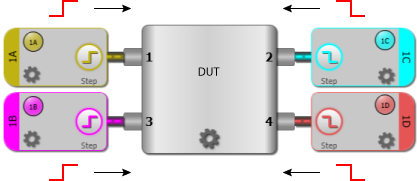
Sixteen different measurements can be made on four-port devices. In addition to the measurements previously described, available measurements include near-end cross talk (S31) and far-end cross talk (S41).
| Time Domain Parameters | S-Parameters | |||||||||
| Stimulus Ports | Stimulus Ports | |||||||||
|---|---|---|---|---|---|---|---|---|---|---|
| 1 | 2 | 3 | 4 | 1 | 2 | 3 | 4 | |||
| Response Ports |
1 | T11 | T12 | T13 | T14 | S11 | S12 | S13 | S14 | |
| 2 | T21 | T22 | T23 | T24 | S21 | S22 | S23 | S24 | ||
| 3 | T31 | T32 | T33 | T34 | S31 | S32 | S33 | S34 | ||
| 4 | T41 | T42 | T43 | T44 | S41 | S42 | S43 | S44 | ||
1-Port Balanced Measurements
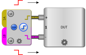
In addition to balanced reflection measurements (for example SDD11), you can perform single-ended reflection measurements on the individual port terminals (S11 and S22) as well as the S21 near-end cross talk measurement between the positive and negative terminals.
2-Port Balanced Measurements
The following tables describe the standard and mixed stimulus measurements.
| Time Domain Parameters | S-Parameters | |||||
| Stimulus Ports | Stimulus Ports | |||||
|---|---|---|---|---|---|---|
| 1 | 2 | 1 | 2 | |||
| Response Ports |
1 | TDD11 | TDD12 | SDD11 | SDD12 | |
| 2 | TDD21 | TDD22 | SDD21 | SDD22 | ||
| Time Domain Parameters | S-Parameters | |||||
| Stimulus Ports | Stimulus Ports | |||||
|---|---|---|---|---|---|---|
| 1 | 2 | 1 | 2 | |||
| Response Ports |
1 | TCC11 | TCC12 | SCC11 | SCC12 | |
| 2 | TCC21 | TCC22 | SCC21 | SCC22 | ||
| Time Domain Parameters | S-Parameters | |||||
| Stimulus Ports | Stimulus Ports | |||||
|---|---|---|---|---|---|---|
| 1 | 2 | 1 | 2 | |||
| Response Ports |
1 | TDC11 | TDC12 | SDC11 | SDC12 | |
| 2 | TDC21 | TDC22 | SDC21 | SDC22 | ||
| Time Domain Parameters | S-Parameters | |||||
| Stimulus Ports | Stimulus Ports | |||||
|---|---|---|---|---|---|---|
| 1 | 2 | 1 | 2 | |||
| Response Ports |
1 | TCD11 | TCD12 | SCD11 | SCD12 | |
| 2 | TCD21 | TCD22 | SCD21 | SCD22 | ||