Channel Step Setup
This Channel Step Setup dialog is opened by clicking a TDR Channel symbol, that is shown connected to a DUT symbol, in the TDR Setup's DUT Layout pane.
Use the Channel Step Setup dialog to control the TDR incident step from TDR modules. The appearance of this dialog changes depending if the Step Setup is single-ended or differential (shown in the following picture).
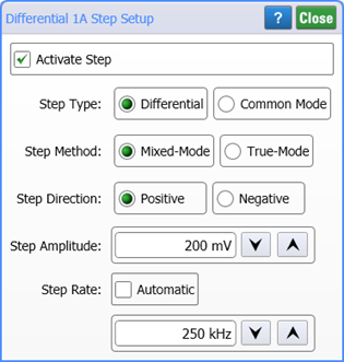
To turn on the TDR step, select Activate Step. This is identical to clicking the ![]() button in the TDR Setup dialog.
button in the TDR Setup dialog.
The Step Direction by default is set to Positive going but can be changed to Negative going if needed for your device.
Use the Step Amplitude field to set the amplitude of the step.
The Step Rate setting affects the repetition rate of the TDR step generator. The default settings is Automatic which varies the repetition rate as you change the time base scale. This prevents multiple steps from appearing on the display. As the TDR rate decreases, TDR measurements can be made on longer transmission lines. You can manually set the repetition rate from 1 Hz to 250 KHz for N1055A-FS1 TDR modules. For N1055A modules that do not have Option FS1, the maximum step repetition rate is 80 kHz.
Decreasing the TDR repetition rate slows down TDR measurements.
Additional Settings for Differential Setups
Select the type of stimulus for the DUT: Differential or Common Mode. The default setting is Differential and the incident steps have the opposite polarity. If Common Mode is selected the two incident steps have the same polarity. The Step Method selection determines how S-parameters are derived: Mixed Mode or True Mode. The default method is Mixed Mode.
- Mixed Mode
- In Mixed Mode, also known as superposition, the differential TDR responses are measured by internally setting both TDR steps to positive polarity and mathematically deriving the responses as if the –step was negative. This allows all other parameters to be mathematically determined. In the TDR Setup dialog, the steps are shown to have opposite polarity. This is the default method.
- True Mode
- In True Mode the differential TDR responses are measured with TDR steps of opposite polarity.
Normally, the Step Type and Step Method settings are automatically determined when you select which time domain parameters and S-parameters that you want to view during the TDR Setup.
General Information on Differential Measurements
Differential TDR involves making measurements on a differential pair of transmission lines. A differential pair is defined as transmission lines that are electromagnetically coupled in some way. PC board designers use differential transmission lines for various applications. Because differential pairs are less affected by interference than a single transmission line, designers use differential lines for applications that are especially sensitive to interference.
There are three ways to make measurements on differential pairs:
- Common stimulus measurement. Introduce a positive-going, same magnitude step on each line. If the lines are symmetric and the impulses are synchronized, there will be no voltage difference present between the two lines. Therefore, coupling of one signal onto the adjacent line does not take place.
- Differential stimulus measurement. Introduce steps of equal magnitude but opposite polarity into the pair. In other words, a positive-going step is launched on one line and an effective negative-going step is launched on the adjacent line. Coupling is important with this measurement stimulus due to the voltage difference between the two lines. If you change a channel's units to ohms (or, % reflection) while using differential stimulus, the channel's trace (negative step) will be inverted in order to avoid displaying negative impedance values.
- Single-ended stimulus measurement. Send a fast step signal down one transmission line while the adjacent line has no voltage (quiet line). This measurement will give the impedance of the active line. The measurement will also provide information about the cross talk between the two lines by measuring the amount of voltage coupled into the quiet line from the signal line.
The three measurement methods yield different characteristic impedance. Which one is the "real" impedance? They all are. Differential pair measurements require that a new concept must be introduced. Differential pairs have an impedance matrix as opposed to single characteristic impedance as in single transmission lines. This matrix is made up of terms corresponding to the amount of coupling that takes place between the lines. The diagonal terms of the matrix are the self-impedance terms. The other elements of the matrix are related to the amount of voltage induced on the quiet line due to current from the active line. The closer the physical distance the two lines are, the larger the coupling terms will be.
The magnitude and phase of the step voltage coupled into each line affects the impedance of the lines. There are only certain voltage magnitude and phase combinations that will propagate down the transmission lines without distortion. These voltage combinations are known as modes. Not coincidentally, the non-distorting modes are the modes that are used for measuring differential pairs as discussed above. The modes are defined as follows:
- Even mode propagates on a line when the differential pair is driven by a common signal.
- Odd mode propagates on a line when a differential pair is driven differentially.
Similarly, the impedance seen by the source on a single line when the differential pair is driven with a common impulse is known as the even mode impedance. The impedance seen by the source on a single line when the differential pair is driven differentially is known as the odd mode impedance.
When using differential TDR, keep in mind that the transmission line properties are greatly influenced by the manner in which they are driven. Always consider the amount of coupling between lines and the propagation velocity.