TDR Setup
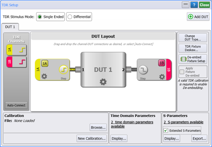
Use the TDR Setup dialog to define, configure, and calibrate a TDR measurement setup and to display Time Domain and S-parameter waveforms. As shown in the following picture, the setup uses a graphical representation of the DUT and TDR head connections. After calibrating your setup, select the T-parameters and S-parameters that you want to view.
To define a TDR/TDT setup
- In the TDR Setup dialog, select the TDR Stimulus Mode: Single Ended or Differential.
- Click Add DUT if you have multple DUT setups to define. You can define up to 16 DUT setups.
- Click Change DUT Type to select the type of DUT that you are using.
- Drag channel symbols shown along the dialog's left side to the DUT ports as needed, as shown in the above picture.
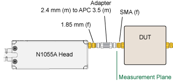
- Make the hardware connections shown in the test setup. You may need to use adapters between the TDR head and the DUT as shown in this example picture.
- In the DUT Layout panel, click these icons to configure the setup:
- Click Step Skew to correct for any skew between TDR channels.
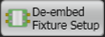
- Click De-embed Fixture Setup to move the measurement plane to the DUT side of a fixture.
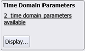
- Click T-Parameters available to select the T-Parameter responses that you want to measure. These selections are shown beneath the DUT Layout panel. The measured T-Parameters can be displayed on Time-Ohms, Time-Volts, and Time-% charts.
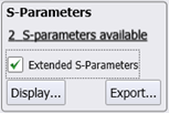
- Click S-parameters available to select the S-Parameter responses that you want to measure. These selections are shown beneath the DUT Layout panel. The measured S-Parameters can be displayed on Magnitude, Phase, and Group Delay charts. Use the Extended S-Parameters setting to extend the maximum S-Parameter stop frequency to 70 GHz on specific N1055A TDR modules identified in the following table. The extended S-Parameter range (>50 GHz to 70 GHz) in the response has no specification or characteristics, but can be informative especially when the setup has been calibrated.
- Click the Display buttons to select which available T- and S-parameters to display.
- Click the Export button to select which available S-parameters to export to a file.
- Click New Calibration to open the TDR Calibration Setup dialog from which you can calibrate your test setup.
- After a calibration has been done, the TDR Setup dialog displays the Rise Time setting from which you can adjust for the stimulus step. You can specify the 10% to 90% rise time of the stimulus steps. The setting range depends on the TDR/TDT module that is installed. Rise time is often used to match the TDR/TDT rise time to the rise time of the actual signal that is expected to be applied to the DUT.
Click on this picture!
| Setup Control | Description |
|---|---|
|
|
Turns a TDR step on and off. You must turn on each step that will be active during some portion of your measurements. This control only appears for channels on N1055A TDR modules.
Turning TDR steps on determines which TDR and TDT responses (time domain parameters) and S-parameters are available for your measurements. License Required. The ability to use S-parameters requires Option 202. |
|
|
Opens the Configure DUT controls for defining custom names for the DUT ports. |
|
|
Opens the Channel Step controls for defining a TDR step's type, method, direction, amplitude, and rate. Normally, these setting are configured automatically and you will not need to change them. |
|
|
For TDR and TDR modules, turns the channel on and off.
If two or more TDR steps are simultaneously on, the channel waveforms include the effects of both step responses and are therefore not an accurate display of individual responses. Always view the time domain parameter waveforms to ensure that you are looking at an accurate waveform. |
If the Extended S-parameters setting was selected when you performed the TDR Setup, when viewing the S-Parameters chart you can toggle the Extended S-parameters setting to display or hide the extended portion of the waveform above 50 GHz.
| Module Option | Extended S-Parameters Setting | |
|---|---|---|
| Off | On | |
| N1055A-32M | 35 GHz | not available |
| N1055A-32F | 35 GHz | not available |
| N1055A-34M | 35 GHz | not available |
| N1055A-34F | 35 GHz | not available |
| N1055A-52M | 50 GHz | 70 GHz 1 |
| N1055A-52F | 50 GHz | 70 GHz 1 |
| N1055A-54M | 50 GHz | 70 GHz 1 |
| N1055A-54F | 50 GHz | 70 GHz 1 |
Not specified within >50 GHz and 70 GHz extended range.
Calibrations can be saved (*.tdrx files) and recalled and applied later to test setups. Use the Browse button to open a previously saved calibration file.
Click Add Dut… to define additional TDR setups. Within the dialog, each setup will be shown in its own tab. Up to 16 DUT setups can be defined.