FlexPLL Measurements
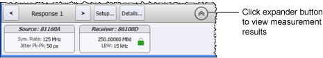
FlexPLL's scalar measurements results are displayed in table beneath the JTF graph. You may need to click on the expander button to see the table. Measurement results are updated at the end of each measurement sweep. The only exception is the Response plot's Transition Density measurement which is updated after each data point acquisition.
Calibration
- Flatness
Response and Memory Plots
Standard Measurements
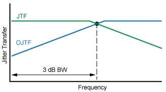
- Bandwidth
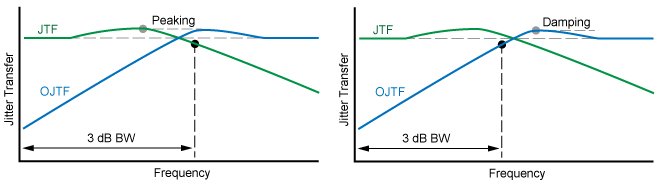
- Peaking Frequency
- Peaking Magnitude
- Transition Density (not available for Memory plots)
Flatness Measurements
Turn the display of these measurements on and off with the Display Flatness Measurements setting.
- Maximum
- Minimum
- Average
Model Plots (Response and Memory)
Turn the display of these measurements on and off with the Model Measurements setting.
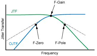
- Gain Frequency
- Zero Frequency
- Pole Frequency
The Jitter Transfer Function (JTF) describes how the input signal (or clock) to the DUT's PLL affects the jitter on the DUT's output signal. Jitter tracking between the DUT's input and output PLL is frequency dependent:T
- Low frequency jitter is transferred to the PLL's output.
- High frequency jitter is not transferred to the PLL's output.
As the jitter on the DUT's input goes beyond the DUT's PLL loop bandwidth, and so decreases, the jitter observed on the recovered clock or signal increases. The Observed Jitter Transfer Function (OJTF) describes the transfer of the input signal's jitter to the jitter observed at the DUT's output. The characteristics of the DUT's PLL affects the observed jitter spectrum seen at the DUT's output. The following drawings show several of the available measurements. Second and third order PLL's are typically implemented in hardware.
with Zero, Pole, and Gain Frequencies