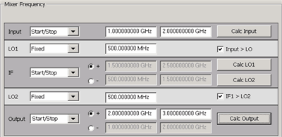
The following dialogs are common to all Converter Apps: FCA, Swept IMDx, IMx Spectrum, NFx, and GCx applications.
Important Note: Connecting your Mixer/Converter DUT to the VNA. RF and IF terminology is NOT used in this topic because the VNA does not know how your DUT is labeled or how it will be used. Instead, the general terms INPUT and OUTPUT are used to describe the following VNA behavior:
|
SettingsFrequency Format Select Start/Stop (Swept) or Fixed. For Linear sweep type, at least one of these must be fixed. For CW or Power, ALL must be Fixed. Frequencies Enter the frequency values for each of the Mixer/Converter ports.
Calc buttons Calculates frequency settings based on your other mixer settings. For example, enter the Input frequency range and LO1 frequency range, then press Calc Output. The VNA will calculate and display the Output frequencies. Input > LO or IF1>LO2 Removes ambiguity when using a Calc button to determine the INPUT frequency. These check boxes are used ONLY when all 3 of the following conditions are TRUE:
Rules for Configuring a MixerA Red message across the bottom of the dialog indicates that one or more of the following settings are invalid:
Apply Applies the settings for your mixer/converter test setup to the measurement. The mixer setup dialog box remains OPEN. OK Applies the settings for your mixer/converter test setup to the measurement. The mixer setup dialog box CLOSES. Cancel Closes the mixer setup dialog box and does NOT apply the settings. See Also |
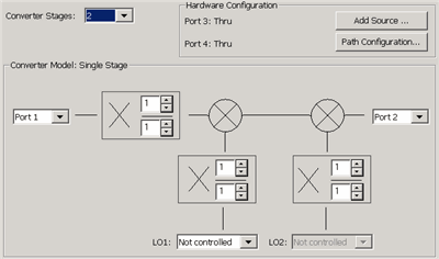
Note: A variation of this dialog is used in the Swept IMDx application. Learn more. Converter Stages Select either 1 or 2-stage converters. Hardware ConfigurationShows the path configuration for Port 3 and Port 4 switches. See Hardware Configurations. Add Source Click to start the External Device Configuration dialog. Path Configuration Click to start the Path Configuration dialog. DUT PortsVMC ONLY - select the PNA port to connect to the DUT output. The DUT input must always be connected to PNA port 1 because of the need for a reference mixer on port 1. All other converter applications - select VNA ports to connect to the DUT input and output. Fractional MultipliersThe combination of (numerator / denominator) forms a fractional value that is multiplied by the input and LO frequency ranges. These values are used to calculate the response frequency of the VNA receiver for the converter output. Use the fractional multipliers to:
The range for the numerator and denominator of a fractional multiplier is from +1 to +10. Negative values are NOT allowed. See Fractional Multiplier examples. LO1 and LO2Select Not controlled to allow an external source to provide a Fixed LO Frequency at all times. Otherwise, select an internal VNA source or External source to be used as the LO. Learn how to Configure an External Device (Source). See AlsoHow to measure a DUT with an Embedded LO
|
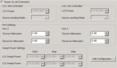
Configures LO Power settings. Power ON (All channels) Check to immediately turn ON or OFF ALL VNA internal RF Sources for all channels. LO1: <source> Power SettingsLO1 Power Sets the power level for LO1. Source Leveling When using internal source for LO1, always set to Internal. LO2: <source> Power SettingsLO2 Power Sets the power level for LO2. Source Leveling When using internal source for LO2, always set to Internal. Port SettingsPort 3 Used when an LO is supplied through the rear panel and out port 3. See Hardware Configurations. Source Attenuator Specifies the port 3 attenuator. This attenuator affects the range of available power into the LO port of the DUT Learn more about Source Attenuation. Receiver Attenuator Set the attenuation for the Port 3 receiver. Learn more about Receiver Attenuation.
Port 4 Used when an LO is supplied through the rear panel and out port 4. See Hardware Configurations. Source Attenuator Specifies the port 4 attenuator. This attenuator affects the range of available power into the LO port of the DUT Learn more about Source Attenuation. Receiver Attenuator Set the attenuation for the Port 4 receiver. Learn more about Receiver Attenuation.
Path Configuration Click to launch the RF Path Configuration dialog.
See AlsoHow to measure a DUT with an Embedded LO
|
Fractional Multiplier Examples
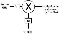
Use the LO fractional multiplier to replicate the action of the third-harmonic mixer so the VNA can accurately calculate the receiver frequency. The input and LO frequencies are known.
Enter these settings in the Mixer Setup dialog box:
Input Start Freq: 30 GHz
Input Stop Freq: 40 GHz
LO Fixed Freq: 16 GHz
Mixer-Product Selector: - (difference)
LOs: 1
LO fractional multiplier: 3/1
INPUT fractional multiplier: 1/1
Click Calculate Output
Results:
Output Start Freq: 18 GHz
Output Stop Freq: 8 GHz
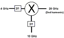
Use the fractional multipliers to tune the VNA receiver frequency to the second harmonic of the mixer's 14 GHz fundamental output. The input, LO, and output frequencies are known.
Enter these settings in the Mixer Setup dialog box:
Input Start Freq: 4 GHz
Input Stop Freq: 4 GHz
LO Fixed Freq: 10 GHz
Mixer-Product Selector: + (Sum) of the input and LO signals
LOs: 1
INPUT fractional multiplier = 2/1
LO fractional multiplier = 2/1
Click Calculate Output
Results:
Output Start Freq: 28 GHz
Output Stop Freq: 28 GHz
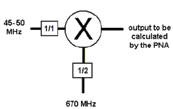
Use the LO fractional multiplier to replicate the action of the divide-by-two mechanism inside the mixer package. Having done this, the VNA can accurately calculate the receiver frequency. The input and LO frequencies are known.
Enter these settings in the Mixer Setup dialog box:
Input Start Freq: 45 MHz
Input Stop Freq: 50 MHz
LO Fixed Freq: 670 MHz
Mixer-Product Selector: + (Sum) of the input and LO signals
LOs: 1
INPUT fractional multiplier = 1/1
LO fractional multiplier = 1/2
Click Calculate Output
Results:
Output Start Freq: 380 MHz
Output Stop Freq: 385 MHz