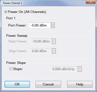
|
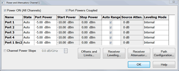
Defines and controls the source power and attenuation for the active channel.
Note: External sources can be controlled from this dialog. Learn more.
Power On (All Channels) Check to enable source power for all channels (same function as RF Power). Only turns power ON if channel power setting is ON or Auto.
Port Powers Coupled
-
Coupled (checked) The power levels are the same at each test port. Set power at any test port and all test ports change to the same power level.
-
Uncoupled (cleared) The power levels are set independently for each test port. Uncouple power, for example, if you want to measure the gain and reverse-isolation of a high-gain amplifier. The power required for the input port of the amplifier is much lower than the power required for the output port. A power sweep can also be performed with uncoupled power. Learn more about Setting Independent Port Power
Name Lists the analyzer test ports.
State
Port Power Sets the power level at the output of the source.
Start / Stop Power Available ONLY when sweep type is set to Power Sweep. Set the start and stop power values of a power sweep. Learn how to set Power Sweep.
-
You can specify whether to maintain source power at either the start power or stop power level at the end of a power sweep. Learn more.
-
A power sweep can be performed with uncoupled power. Different power ranges can be swept in the forward and reverse directions.
Auto Range Check to allow the analyzer to select the optimum attenuation value to achieve the specified test port power.
Clear to manually set the attenuation for each port. Type or select the attenuation value in the adjacent Attenuator Control box.
When using manual attenuation (Auto Range cleared), Port Power can be set within a 60 dB range. For example:
-
With 0 dB of manual attenuation, Port Power can be set from -30 dBm to +30 dBm.
-
With 10 dB of manual attenuation, Port Power can be set from -40 dBm to +20 dBm, and so forth.
Important Note: The available power range can also be adjusted AUTOMATICALLY by a Source Power Calibration, Guided Power Cal, or Power Compensation. If you are NOT seeing the range that you expect, or the correct power level at your DUT, view the Power Offset column in the Power Limits and Offsets dialog.
Source Attenuator When Port Powers are Uncoupled, manual attenuator control allows you to set a wide range of power levels by setting the attenuation. See Setting Independent Port Power. Also use manual attenuation control when a measurement requires a very good impedance match with the source, such as with oscillators or conditionally unstable amplifiers. Choose an attenuation level of 10 dB or more to ensure the best source match.
-
Attenuators or other mechanical switches are NOT allowed to switch continuously. Learn more.
-
When Port Powers are Coupled, changing one port Attenuation Control value changes all port values.
Default Source Attenuation Based on Measurement Class
The table below lists the default source attenuation values (dB) for each port, based on the selected measurement class. These are the initial source attenuation values that appear when you open the Power and Attenuators dialog box.
|
Meas.
Class
|
Port 1
|
Port 2
|
Src2
Out1
|
Src2
Out2
|
Port 1
Src2
|
|
Std.
|
0
|
0
|
0
|
0
|
0
|
|
AHP
|
0
|
0
|
0
|
0
|
0
|
|
GCA
|
0
|
0
|
0
|
0
|
0
|
|
DIQ
|
0
|
0
|
0
|
0
|
0
|
|
IMS
|
0
|
10
|
0
|
0
|
0
|
|
IMD
|
0
|
10
|
0
|
0
|
0
|
|
MOD
|
0
|
0
|
0
|
0
|
0
|
|
NF
|
20
|
10
|
0
|
0
|
20
|
|
PN
|
0
|
0
|
0
|
0
|
0
|
|
SA
|
0
|
0
|
0
|
0
|
0
|
|
TDR
|
NA
|
NA
|
NA
|
NA
|
NA
|
|
GCX
|
0
|
0
|
0
|
0
|
0
|
|
IMSX
|
0
|
10
|
0
|
0
|
0
|
|
IMDX
|
0
|
10
|
0
|
0
|
0
|
|
MODX
|
0
|
0
|
0
|
0
|
0
|
|
NFX
|
20
|
10
|
0
|
0
|
20
|
|
SMC
|
5
|
5
|
0
|
0
|
5
|
|
VMC
|
5
|
5
|
0
|
0
|
5
|
|
Note: Because the reference receiver is not in the attenuation path, there is more power at the reference receiver than at the test port by the amount of source attenuation.
By default, ALL VNA models mathematically offset the reported power at the reference receivers by the amount of source attenuation. See Block diagram.
A preference can be set to NOT mathematically offset the reported power of the reference receiver by the amount of source attenuation.
Learn how to set the preference.
|
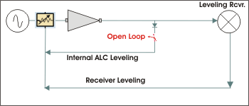
Leveling Mode (ALC Hardware Softkey)- Refer to the following diagram:
-
Internal - ALC leveling. Power level within an attenuator setting is limited to the ALC Range. See Source Unleveled.
-
Open Loop - No ALC and NO Receiver Leveling. (Used during pulse conditions with the internal source modulators). NOT available on N523x models. No leveling is used in setting the source power. The lowest settable power, without attenuation, is limited to -30dBm. The source power level accuracy is very compromised. Use a source power calibration to make the source power somewhat more accurate.
-
Receiver Rx - Receiver Leveling. Select a receiver to use for leveling the source. Learn more.
-
Note: Receiver Leveling can be used with EITHER Internal ALC or Open Loop. See Enable ALC Hardware on the Receiver Leveling dialog.
Channel Power Slope
Helps compensate for cable and test fixture power losses at increased frequency. With power slope enabled, the port output power increases (enter positive value) or decreases (enter negative value) as the sweep frequency increases.
Slope Select to set the power slope. Clear to set power slope OFF.
Power slope is computed and applied from 0 GHz – not from the measurement start frequency.
For example, with the following measurement settings:
The power into the DUT from 10 GHz to 20 GHz is 10 dBm sloping to 20 dBm
Offset and Limits Launches the Power Offset and Limits dialog.
Receiver Leveling Launches the Receiver Leveling dialog.
Receiver Attenuator Launches the Receiver Attenuator dialog.
Path Configurator Launches the Path Configurator dialog.
Source Unleveled
When the power level that is required at a test port is higher than can be supplied, a Source Unleveled error message appears on the screen and the letters LVL appear on the status bar.
To perform a power sweep, the range of power is usually limited to the range of the Automatic Leveling Control (ALC) loop. (The PNA-X allows a very wide power range using Open Loop).
Specifications guarantee the ALC power range over which power can be supplied without an unleveled indication. However, the actual achievable power range on your analyzer is probably greater than the specified range.
How to calculate the specified achievable power range
From the specifications for a frequency span from 15 GHz to 20 GHz:
For this frequency range the specified power range is calculated as:
When using Source Attenuators:
-
with 10dB of attenuation, this becomes -18 dBm to -35 dBm
-
with 20dB of attenuation, this becomes -28 dBm to -45 dBm, and so forth.
To resolve an unleveled condition, change either the Test Port Power or Attenuator setting.
Important Note: The available power range can also be adjusted AUTOMATICALLY by a Source Power Calibration, Guided Power Cal, or Power Compensation. If you are NOT seeing the range that you expect, or the correct power level at your DUT, view the Power Offset column in the Power Limits and Offsets dialog.
Setting Independent Port Power
You can uncouple port power and specify different power levels at each test port. There are a few things to consider when setting independent port powers.
-
Does your required high and low power levels fall within the specified Min and Max power range of the analyzer? See Unleveled Indicator. If they do not, you may need to use the internal Source Attenuators.
-
Does the analyzer have source attenuators? If so, how many source attenuators? Some VNA models have one attenuator for each port. In most multiport VNA systems, the attenuators are shared by at least two test ports. See VNA Options to see the availability and range of source attenuation on your VNA.
|
Note: To prevent premature wear, attenuators or other mechanical switches are NOT allowed to switch continuously.
These mechanical devices are set for the entire channel. When more than one channel is used, and a mechanical device setting is NOT the same for all channels, only the ACTIVE channel is allowed to sweep. All other channels are NOT allowed to sweep (Blocked).
Learn how to view the settings of all mechanical devices.
|
Setting Port Power On/Off for the Second source and Multi Module/Unit configuration
When the unit has the second source capability or multi module/unit configuration in PXI/USB VNA, Source power ALWAYS ON can be applied for each source group.
The following dialog shows an example of three module configuration of six, four and two port PXI VNAs. In this case, there are three independent source group, port 1to 6, 7 to 10 and 11 to 12. You can set one port in each group at ON state.
Optimum Attenuation Value
The attenuator has different positions, allowing a wide range of power levels. The number of power ranges available is determined by the source attenuation installed in your VNA. See VNA Options to see the availability and range of source attenuation on your VNA.
-
Each range has a total specified span (50 dB in the following Attenuation Values graphic ).
-
The optimum setting is the middle of the range. This range provides the best accuracy and performance of the source leveling system. The optimum ranges are the blue regions in the following graphic.
-
An attenuator setting can be selected manually or automatically. If automatic is selected, the blue optimum ranges (shown in the following graphic) are used.
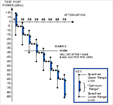
Note: Error correction is fully accurate only for the power level at which a measurement calibration was performed. However, when changing power within the same attenuator range at which the measurement calibration was performed, ratioed measurements can be made with nearly full accuracy (non-ratioed measurements with less accuracy).
|
Receiver Attenuators dialog box help
|
|
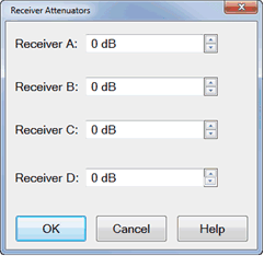
Receiver Attenuators are offered as an option. Learn more.
Type or select independent attenuation values for each receiver.
-
Receiver A is at Test Port 1
-
Receiver B is at Test Port 2
-
Receiver C is at Test Port 3
-
Receiver D is at Test Port 4
Receiver Attenuation is used to protect the VNA test port receivers from damage or compression. Receiver attenuation causes the reported power at the receiver to be less than the power at the test port by the specified amount of attenuation.
When an external test set is connected, Receiver Attenuation control is only available for the physical receivers in the VNA. Switching receiver attenuation using logical receiver notation is NOT allowed.
CAUTION! You can damage the analyzer receivers if the power levels exceed the maximum values.
|
Power ON and OFF during Save / Recall, User Preset, and Preset
To protect your DUT from being inadvertently powered ON, the following RF Power ON/OFF settings occur:
If power is OFF when an instrument state is saved, then power will always be OFF after the instrument state is recalled.
If power is ON when an instrument state is saved, and the current power setting is OFF, then power will be OFF after the instrument state is recalled.
If power is OFF when a User Preset is saved, then power will always be OFF after a User Preset.
If power is ON when a User Preset is saved, and the current power setting is OFF, then power will be OFF after a User Preset.
Instrument Preset sets power ON by default.
This can be changed with a Preference setting so that, if the current power setting is OFF, then power will be OFF after Preset.
Power ON and OFF during Sweep and Retrace
The frequency range of the VNA covers several internal frequency bands. The higher the frequency range of the VNA, the larger the number of bands. For example, a 9 GHz VNA has 6 frequency bands, a 50 GHz VNA has 25 frequency bands. See the frequency band crossings.
Power to the DUT is turned OFF during band changes to avoid causing power spikes to the DUT.
Retrace occurs when the source gets to the end of your selected frequency span and moves back to the start frequency. Power to the DUT is again turned OFF when retracing across frequency bands.
The following power ON/OFF states occur for various stimulus settings:
-
Single band sweep - The power ON/OFF state to the DUT during retrace is determined by a preference setting.
-
Multi-band sweep - The power to the DUT is turned OFF while sweeping across a band crossing. It is turned OFF again during retrace.
-
Power sweep - Power sweep is always done at a single frequency, Therefore, like item 1, the power ON/OFF state to the DUT during retrace is determined by a preference setting
-
Single sweep:
-
-
Manual trigger mode - At the end of a multiband sweep, power is turned OFF during retrace, and then power is turned back ON before arming for the next trigger.
-
Hold mode - Power can be ON or OFF depending on when and how Hold mode is entered. However, power can be immediately turned OFF manually or remotely.
Caution: Avoid expensive repairs to your analyzer. Read Electrostatic Discharge Protection.
|
