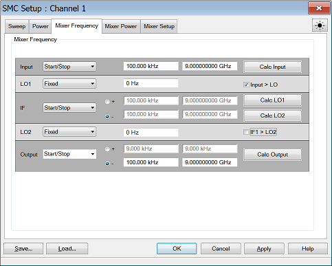
Mixer/Converter Setup


The following dialogs are common to all Converter Apps: FCA, Swept IMDx, IMx Spectrum, NFx, and GCx applications.

Note: Swept IMDx, IMx Spectrum, NFx are supported by PNA only. GCx is currently not supported on the M9370A/71A/72A/73A/74A/75A.

Important Note: Connecting your Mixer/Converter DUT to the VNA.

RF and IF terminology is NOT used in this topic because the VNA does not know how your DUT is labeled or how it will be used. Instead, the general terms INPUT and OUTPUT are used to describe the following VNA behavior:

  • INPUT - the stimulus frequencies BEFORE conversion by your DUT.

  • OUTPUT - the response frequencies, AFTER conversion (either UP or DOWN) by your DUT. Specify UP or DOWN conversion using the + or - symbol for each output.


Mixer Frequency tab help

Settings

Frequency Format   Select Start/Stop (Swept) or Fixed. For Linear sweep type, at least one of these must be fixed. For CW or Power, ALL must be Fixed.

Frequencies  Enter the frequency values for each of the Mixer/Converter ports.

Mixer-Product Selector  Determines whether the receivers will tune to the Sum (+) or the Difference ( - ) of the Input and LO frequencies.

Calc buttons  Calculates frequency settings based on your other mixer settings. For example, enter the Input frequency range and LO1 frequency range, then press Calc Output.  The VNA will calculate and display the Output frequencies.

Input > LO or IF1>LO2  Removes ambiguity when using a Calc button to determine the INPUT frequency.

These check boxes are used ONLY when all 3 of the following conditions are TRUE:
(If ALL 3 are NOT true, the VNA does not read these check boxes).

  1. Difference (Low) sideband is selected for the corresponding Calculate button AND

  2. Output frequency is less than the LO frequency AND

  3. One of the Calculate buttons are used to calculate the Input frequency.

Rules for Configuring a Mixer

A Red message across the bottom of the dialog indicates that one or more of the following settings are invalid:

  • Either ALL ranges (Input, LO, Output) must be Fixed, or ONE Range fixed. TWO ranges can NOT be Fixed or THREE ranges can NOT be Swept.

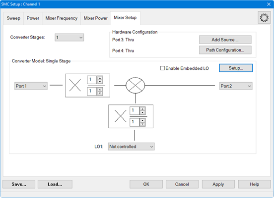
  • For determining a valid mixer configuration with 2 LOs, one Fixed LO and one Swept is equivalent to having a single-stage Swept LO. To configure a 2-stage LO, select Converter Stages: 2 on the Mixer Setup tab.

  • INPUT or OUTPUT frequencies cannot be outside the range of the VNA.

  • Any combination of INPUT and LO which results in an OUTPUT that sweeps through Zero Hz is NOT allowed.

About Mixer Configuration Files (*.mxr, *.mxrx, or *.csv)

Save  Saves SOME of the mixer settings to a *.mxr, *.mxrx, or *.csv file.

Load  Recalls a previously-configured mixer *.mxr, *.mxrx, or *.csv file.

Note: By default, mixer configurations are saved to a *.mxrX file. Previously, they were saved to a *.mxr file.

ONLY *.mxrx and *.csv files allow saving segmented sweep mixer setups. Currently, only allows segmented sweeps. In all other respects, these new file types are completely backward compatible with *.mxr files.

What Mixer Settings are Saved?

  • Sweep Type, frequency, and power settings.

  • With Segment Sweep Type, all segment settings are saved.

Converter App Compatibility

The mixer setup files that are used with FCA, NFx, and GCx for PNA ARE compatible. However, *.mxr(x) files created in IMDx contain information that is NOT included with other *.mxr(x) files.

    External Sources

    A *.mxr(x) file includes an LO source name. However, It does NOT include the LO Source configuration.


    CSV Files

    Note: Mixer CSV Format is a Licensed Feature. Learn more about Licensed Features.

    Mixer configuration files can be saved as a *.csv file. This format was implemented to be used for setting up mixer segments. Start with the GUI to set up mixer settings and to create the first segment then save it as a *.csv file. The GUI can be used to set up multiple segments but is not as convenient as editing an existing Excel *.csv file directly.

    The *.csv file has two main categories:

    • #BaseSetting
    • #MixerSegments

    Note: The CSV file also supports adding comments. All comments must be added before the #BaseSetting row in the CSV file.

    #BaseSetting captures the following fields:

    Default Columns1

    NumberOfStages2

    PortPowerCoupled

    OutputNumerator

    SegmentSweepMode

    InputNumerator

    OutputDenominator

    ReduceIFBandOFF

    InputDenominator

    PowerMode3

    CenterSpan

    LO1Numerator

    XAxisRange

    AvoidSpurs

    LO1Denominator

    LO1 (auxiliary setting)

    PowerCalibrationOn


    Conditional Columns (auxiliary setting): Swept IMD Converter

    IMDXSweepType


    RF2TonePower

    IMDXVersion


    RF2StartPower

    RF2


    RF2StopPower

    Conditional Columns: Dual Converter Stage


    LO2Numerator


    LO2Denominator


    LO2 (auxiliary setting)


    Conditional Columns: PowerMode is Swept, and Converter is not IMDX4

    InputStartPower


    LO1PowerMode

    InputStopPower


    LO1StartPower

    OutputStartPower


    LO2PowerMode (in dual converter stage)

    OutputStopPower


    LO2StartPower (in dual converter stage)

    Conditional Columns: IMDX Converter5

    InputStartPower


    LO1PowerMode

    InputStopPower


    LO1StartPower

    OutputStartPower


    LO2PowerMode (in dual converter stage)

    OutputStopPower


    LO2StartPower (in dual converter stage)

    1 Default columns are always included in the csv.

    2 NumberOfStages (previously IsSingleStage) has been moved under ‘#BaseSettings’ and will be used to set converter stage value for each segment.

    3 InputPowerMode, OutputPowerMode, LO1PowerMode, and LO2PowerMode (in dual converter stage) have been consolidated into PowerMode in the CSV.

    4 Start and Stop powers for Input, Output, LO1, and LO2 (in dual converter stage) are included in the CSV when PowerMode is Swept. When PowerMode is Fixed,
    these values will be based on the power values from the segments.

    5 For IMDX converter, Start and Stop powers for Input, Output, LO1, and LO2 are included regardless of value in PowerMode column.


    #MixerSegments captures the following fields:

    Default Columns

    SegmentNumber

    Dwell

    LO1MixingMode

    State

    InputRangeMode

    InputGreaterThanLO1

    IFBandwidth

    LO1RangeMode

    OutputRangeMode

    Conditional Columns: Segment Sweep Mode


    NumberOfPoints


    Conditional Columns: PowerMode in Base Setting is Fixed


    InputPower


    LO1Power


    OutputPower


    Conditional Columns: Dual Converter Stage

    LO2Power


    LO2RangeMode

    IFRangeMode


    LO2MixingMode


    InputGreaterThanLO2

    Conditional Columns: Based on InputRangeMode Value

    Value

    Columns

    Fixed (for all Segments)1

    InputFixedFreq

    Swept (for all Segments)2

    InputStartFreq

    InputStopFreq

    Fixed/Swept (for all Segments)3

    InputFixedFreq

    InputStartFreq

    InputStopFreq

    Conditional Columns: Based on LO1RangeMode Value

    Value

    Columns

    Fixed (for all Segments)

    LO1FixedFreq

    Swept (for all Segments)

    LO1StartFreq

    LO1StopFreq

    Fixed/Swept (for all Segments)

    LO1FixedFreq

    LO1StartFreq

    LO1StopFreq

    Conditional Columns: Based on OutputRangeMode Value

    Fixed (for all Segments)

    OutputFixedFreq

    Swept (for all Segments)

    OutputStartFreq

    OutputStopFreq

    Fixed/Swept (for all Segments)

    OutputFixedFreq

    OutputStartFreq

    OutputStopFreq

    Conditional Columns: Based on IFRangeMode Value (dual stage only)

    Fixed (for all Segments)

    IFFixedFreq

    Swept (for all Segments)

    IFStartFreq

    IFStopFreq

    Fixed/Swept (for all Segments)

    IFFixedFreq

    IFStartFreq

    IFStopFreq

    Conditional Columns: Based on LO2RangeMode Value (dual stage only)

    Fixed (for all Segments)

    LO2FixedFreq

    Swept (for all Segments)

    LO2StartFreq

    LO2StopFreq

    Fixed/Swept (for all Segments)

    LO2FixedFreq

    LO2StartFreq

    LO2StopFreq

    1 If SegmentSweepMode is true and all the segments have InputRangeMode set to Fixed, then only InputFixedFreq column will be displayed in the CSV.
    If SegmentSweepMode is false and the non-segment configuration’s InputRangeMode is Fixed, the behavior will be the same. This behavior will be true for
    Output, LO1, IF and LO2 as well.

    2 If SegmentSweepMode is true and all the segments have InputRangeMode set to Swept, then only InputStartFreq and InputStopFreq columns will be displayed.
    If SegmentSweepMode is false and the non-segment configuration’s InputRangeMode is Swept, the behavior will be the same. This behavior will be true for Output, LO1,
    IF and LO2 as well.

    3 If SegmentSweepMode is true and the segments have a mix InputRangeMode, i.e. segment #1 has Fixed and segment #2 has Swept, then InputFixedFreq, InputStartFreq
    and InputStopFreq columns will be displayed in the csv. This will be true for Output, LO1, IF and LO2 as well.


    The following is an example of an SMC segment sweep csv file:


    For a procedure, refer to How to configure multiple segments using the GUI and Excel *.csv file.


    Apply  Applies the settings for your mixer/converter test setup to the measurement. The mixer setup dialog box remains OPEN.

    OK  Applies the settings for your mixer/converter test setup to the measurement. The mixer setup dialog box CLOSES.

    Cancel  Closes the mixer setup dialog box and does NOT apply the settings.


    Mixer Setup tab help

    Converter Stages  Select either 1 or 2-stage converters.

    Hardware Configuration

    Add Source  Click to start the External Device Configuration dialog.

    DUT Ports

    Select VNA ports to connect to the DUT input and output.

    Note: In M9485A, Only ports 1 to 4 can be set even if your unit has more than 4-port configuration.

    Fractional Multipliers

    The combination of (numerator / denominator) forms a fractional value that is multiplied by the input and LO frequency ranges. These values are used to calculate the response frequency of the VNA receiver for the converter output. Use the fractional multipliers to:

    • simulate the action of harmonic mixers

    • simulate the action of multipliers and dividers that may exist in your test setup

    • tune the VNA receiver frequency to a harmonic of the mixer/converter

    The range for the numerator and denominator of a fractional multiplier is from +1 to +10. Negative values are NOT allowed.

    See Fractional Multiplier examples.

    LO1 and LO2

    Select Not controlled to allow an external source to provide a Fixed LO Frequency at all times. Otherwise, select an internal VNA source or External source to be used as the LO. Learn how to Configure an External Device (Source).

    When the unit has the second source capability or multi module/unit configuration in PXI/USB VNA, the second source and ports in other module can be selected as LO.

    Embedded LO

    The Embedded LO feature allows you to make measurements of mixers that have a FIXED LO inside the DUT.

    Enable Embedded LO  Check to enable measurement of the Embedded LO.

    Setup... button  Accesses the Embedded LO dialog. See Embedded LO dialog box help for descriptions of the settings.

    See Also

    How to measure a DUT with an Embedded LO

    Learn about these buttons.


    Mixer (LO) Power tab help

    Configures LO Power settings.

    Power ON (All channels)  Check to immediately turn ON or OFF ALL VNA internal RF Sources for all channels.

    LO1 Power  Sets the power level for LO1.

    LO2 Power  Sets the power level for LO2.

    Swept Power Settings Set the power sweep setting.

    Path Configuration (PNA only)  


    Learn about these buttons.


    Fractional Multiplier Examples

    Example 1

    Use the LO fractional multiplier to replicate the action of the third-harmonic mixer so the VNA can accurately calculate the receiver frequency. The input and LO frequencies are known.

    Enter these settings in the Mixer Setup dialog box:

    Click Calculate Output

    Results:


    Example 2

    Use the fractional multipliers to tune the VNA receiver frequency to the second harmonic of the mixer's 14 GHz fundamental output. The input, LO, and output frequencies are known.

    Enter these settings in the Mixer Setup dialog box:

    Click Calculate Output

    Results:


    Example 3

    Use the LO fractional multiplier to replicate the action of the divide-by-two mechanism inside the mixer package. Having done this, the VNA can accurately calculate the receiver frequency. The input and LO frequencies are known.

    Enter these settings in the Mixer Setup dialog box:

    Click Calculate Output

    Results: