Gain Compression is measured on Converters in the same manner as it is measured in Amplifiers. Also, the Mixer/Converter setup is very similar to that of SMC (Scalar Mixer Converter application).
In this topic (unique for GCX):
The following Gain Compression for Amplifiers information is relevant for learning about GCX:
The following dialog setup tabs are shared with other applications:
Frequency tab (GCA topic)
Power tab (GCA topic)
Compression tab (GCA topic)
Safe Sweep Mode dialog (GCA topic)
Mixer Frequency tab (separate topic)
Mixer Setup tab (separate topic)
Mixer (LO) Power tab (separate topic)
GCX requires Option S93086A/B (Gain Compression).
Limitations:
Number of points limited to 100,001 for two-dimensional acquisitions, 50,000 points for SMART Sweep.
Linear and CW sweep ONLY - No Power, Log, or Segment sweep. Learn more.
GCX does NOT provide any built-in image rejection techniques. You should provide image rejection hardware if necessary.
Stepped sweep mode only.
Does NOT support Narrowband Pulse measurements using the integrated Pulse setup dialogs.
The following VNA features are NOT available with Gain Compression on Converters:
Save Formatted Citifile data.
Some Fixturing Features
External Test Set Control (Option S93551A/B)
Independent IFBW, Power Levels, or Sweep Time in a segment table is NOT supported.
The following is a general procedure for performing a GCX measurement. The challenge with GCX is configuring a measurement that yields the true compression performance of YOUR DUT. This requires knowledge of the Gain Compression and Mixer settings, and knowledge of the DUT.
See specific dialog boxes below for details.
Disconnect the DUT if preset or default power levels may damage the VNA or DUT.
Preset the VNA, or configure a suitable User Preset that will be safe in case the DUT is connected.
Create a GCX channel. Learn how. The default trace is SC21.
Start the GCX Setup dialog and configure the measurement settings based on the DUT, adapters, attenuators, booster amplifiers, and fixtures to be used in the measurement. To start the dialog, click Stimulus, then Frequency, then GCX Setup. Learn about the setup dialogs.
Save the instrument state (optional).
Connect the DUT. Inspect the measurement to ensure the DUT is operating as expected.
Add GCX compression and mixer parameter traces. Learn more.
Adjust the measurement settings to yield satisfactory compression results. See GCA Measurement Tips.
Start and complete the GCX Calibration wizard.
Press Meas > S-Param > Meas Class....
Select Gain Compression Converters, then either:
OK delete the existing measurement, or
New Channel to create the measurement in a new channel.
A default SC21 measurement is displayed. To select additional parameters to display, press Trace, select a trace, press Meas, then select a parameter. Learn more about GCX Parameters.
How to start the Gain Compression for Converters Setup dialog |
|
|
Using Hardkey/SoftTab/Softkey |
Using a mouse |
|
|
The following are the Valid Sweep Type / Mixer Configurations.
|
Sweep Type |
Input |
LO |
Output |
|
Linear |
Swept |
Fixed |
Swept |
|
Swept |
Swept |
Fixed |
|
|
CW |
Fixed |
Fixed |
Fixed |
|
Fixed |
Swept |
Swept |
For determining a valid mixer configuration with 2 LOs, one Fixed LO and one Swept is equivalent to having a single-stage Swept LO.
If you create an invalid Sweep Type / Mixer Configuration, a red message appears like the following:
![]()
If this occurs, change the Sweep Type on the Frequency tab.
See other rules for configuring a mixer.
|
Note: The following table assumes: DUT Input = VNA port 1 and DUT Output = VNA port 2. When the Port mapping is different, the parameters in GCX are updated accordingly. For example, with Input = port 2 and Output = port 1, then "CompIn12" would be displayed. |
|
Parameter |
Description |
|
Mixer Parameters |
|
|
SC21 |
Linear Conversion Gain |
|
SC12 |
Reverse Conversion Gain |
|
S11 |
Input Match |
|
S22 |
Output Match |
|
Compression Parameters |
|
|
CompIn21 |
Input power at the compression point. |
|
CompOut21 |
Output power at the compression point. |
|
CompGain21 |
Gain at the compression point. |
|
CompS11 |
Input Match at the compression point. |
|
RefS21 |
Linear Gain value used to calculate the compression level. This is calculated differently depending on the compression method. |
|
DeltaGain21 |
CompGain21 MINUS Linear Gain (in Log Mag format). This trace can be used to learn a lot about the DUT compression point. Learn more. |
|
Unratioed - Absolute test port receiver measurements. Learn more. |
|
|
IPwr |
Input power measured at DUT-IN @ Input frequency |
|
OPwr |
Output power measured at DUT-OUT @ Output frequency |
|
RevIPwr |
Input power measured at DUT-OUT @ Output frequency |
|
RevOPwr |
Output power measured at DUT-IN @ Input frequency |
|
ADC Parameters - Learn more. |
|
|
AI1 |
Measured at the specified Linear Input level. |
|
AI2 |
Measured at the specified Linear Input level. |
|
CompAI1 |
AI1 at Compression |
|
CompAI2 |
AI2 at Compression |
All of the GCX Setup tabs are shared with other applications.
A GCX Cal is conceptually the same as a Gain Compression Calibration. This includes the ability to perform or downgrade to an Enhanced Response Cal. Learn how.
The following Guided Cal Wizard pages are unique to GCX:
|
Waveguide/In-fixture/On-Wafer Setup Starts the following dialog box. Independent power cals for input and output ports (no thru) Check if a Thru standard is NOT available. During the power cal, you will be prompted to connect the power sensor to the Input, then the Output port. Additional Power Cal StepsEnable LO1 / LO2 Power Cal Check when LO1 / LO2 is controlled (on the Mixer Setup tab) to perform a Power Cal on the source. Note: Phase Correction is NOT allowed for GCX measurements. |
|
This dialog box appears ONLY if you checked the Waveguide/In-fixture/On-Wafer Setup box in the previous Cal Setup dialog. Allows you to embed or de-embed circuit networks on the input and output of your mixer under test. For Network1 (Input) and Network2 (Output) select Embed, De-embed, or None. Browse Click to navigate to the .S2P file that models the network to embed or de-embed. To Embed or De-embed
|
|
Allows you to specify the connector type and Cal Kit for each DUT port. Port n For each listed VNA port, specify the DUT connector type and gender, and the Cal Kit to use. input pwr sensor Specify the connector type of the power sensor. Select Ignored to not compensate for the effects of the adapter that may be necessary to connect the power sensor to the input reference plane. output pwr sensor Available when Independent power cals for input and output ports is checked on the GCX Calibration Setup dialog. Specify the connector type of the power sensor. Select Ignored to NOT compensate for the effects of an adapter that may be necessary to connect the power sensor to the output reference plane. De-embed input power sensor adapter Check to measure, then remove the effects of the adapter that is used to connect the power sensor to the calibration reference plane. Source Cal Settings Click to start the Source Cal Settings dialog. These settings allow you change ALL Source Cal and Power Meter settings. Note: If your DUT connectors are:
Modify Cal Check, then click Next, to start the Modify Frequency Cal dialog. |
How to save GCX dataWith a GCX Compression trace active: |
|
|
Using Hardkey/SoftTab/Softkey |
Using a mouse |
|
|
Notes
This data type can be read by spreadsheet programs, such as Microsoft Excel.
Data from the last complete sweep is saved to the specified *.csv file.
If calibration is turned ON when the file is saved, then all data is calibrated. Otherwise, raw data is saved.
All *.csv data saves include a reference power level sweep at the beginning of each frequency data.
GCX Sweep Data (*.csv) includes sweep data.
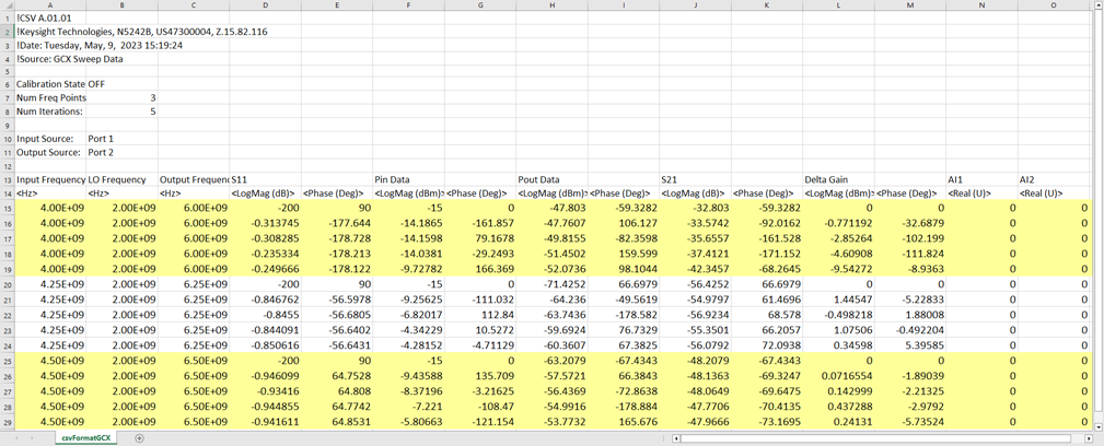
SMART Sweep data with 5 iterations and 3 frequency points. The yellow highlight is added here for readability.
When Linear Input Power EQUALS Start Power, then the number of data points (rows)/ freq = num power points.
When Linear Input Power does NOT EQUAL Start Power, the number of data points (rows)/ freq = num power points + 1.
Make these selections on the GCA/GCX Power tab dialog.