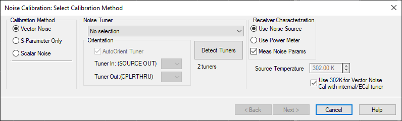
Calibration for Noise Figure on Amplifiers and Converters (NFX)


Note: The M937xA/P937xA does not support this function.

This topic discusses calibration for both Noise Figure on Amplifiers and Noise Figure on Converters (NFX).

See Also

Noise Figure and TRL Cal

See Noise Figure Applications

Noise Figure Calibration Overview

Note: Noise Figure results are NOT at all accurate without a Noise Figure calibration.

NFX Calibration

Noise Figure calibration is very similar for both amplifiers and converters (NFX).

Calibrating the Noise Receivers

Note:  The term 'noise receiver' is used here to refer to the receiver that is used to measure noise.

The noise figure calibration process is different depending on if a Noise Source or a VNA source (calibrated with a power meter) is used to calibrate the noise receiver.

Using a Power Meter

When 'Use Power Meter' is selected on the 'Select Cal Method' dialog, a power meter is used in place of a noise source to characterize the noise receiver. IMPORTANT: The power cal step must be completed first when acquiring the calibration.

The process happens in three steps:

  1. A Source Power Cal is performed at the port connected to the DUT’s input, with a power level that is specified on the first measurement step of the calibration wizard.

  2. A THRU connection is made from the calibrated source port to the specified noise receiver port. The gain of the noise receiver is then measured, as well as the receiver’s noise floor.

  3. With the THRU connection in place, the swept-frequency response of the noise bandwidth filter is measured. Since the noise receiver uses double-sideband homodyne mixing, the user sees a symmetrical response representing the low- and high-side responses, with a notch in the middle that nulls out the DC response. From the measured filter shape, the equivalent noise bandwidth is calculated. This information combined with the data from step 2 gives the gain-bandwidth product and noise figure of the noise receiver.

The following are variations to this process .

    1. Step 3 (measure the frequency response of the noise bandwidth filter) is always performed, over the frequency range specified in the noise figure channel.

    2. The gain-bandwidth information is contained within the noise figure calset.

    3. Noise averaging is not automatically turned on.

    Using a Noise Source (See Noise Source requirements).

    A Noise Source is a device that generates two very consistent levels of noise over its operating frequency range:

    These levels are measured by the Noise Source manufacturer and provided in table and electronic format with each Noise Source by serial number. The electronic file is known as the ENR (Excess Noise Ratio) file.

    1. The Noise Source is connected to the noise receiver through test port 2.

    Note: For highest accuracy, the noise source should be connected as close as possible (the least amount of electrical loss) to the VNA port 2 connector. This causes the largest difference between the Noise Source HOT (on) and COLD (off) settings.

    1. The Noise Source is measured by the noise receivers at each measurement frequency. The differences between the known ENR noise levels and the measured noise levels are the noise error terms. These values are removed from subsequent noise measurements.  

    2. During the Noise Source measurements, noise averaging and noise bandwidth is automatically turned ON to the values that you specify. Learn more about Noise Averaging.  

    Following the Noise Receiver Cal

    How to Perform a Noise Figure Calibration

    Using Hardkey/SoftTab/Softkey

    Using a mouse

    1. Press CAL > Main > Smart Cal....

    1. Click Response

    2. Select Cal

    3. Select Smart Cal...


    The following Cal Wizard pages are unique to noise figure calibration. The remaining pages that are presented are the same as those in the standard Cal Wizard SmartCal.

    Select Calibration Method dialog box help

    Calibration Method

    • Vector Noise - Comprehensive noise figure calibration (Not available on M9485A)

    • S-Parameter Only - Does NOT calibrate the noise receivers.  (Not available on M980xA,P50xxA/B,M983xA)

    • Scalar Noise - Calibration for scalar noise figure measurements. Learn more.

    Noise Tuner

    Note: The M9485A does not support this function.

    • Not available when Scalar Noise is selected.

    • Select from the ECal modules that are connected to the USB. Learn More.

    Orientation

    Note: The M9485A does not support this function.

    AutoOrient Tuner  Check to allow the noise tuner orientation to be auto-detected. When cleared, use the following two fields to provide manual orientation of the noise tuner.

    Tuner In (SOURCE OUT)  /  Tuner Out (CPLRTHRU): Specify the ECal module labels that are connected to the VNA front panel jumper connectors. Learn how to connect the noise tuner.

    Detect Tuners  Click to re-detect the Noise Tuners (ECal modules) that are connected to the USB.  If the ECal module is not detected, check the USB connection, then click this button. The label below the button indicates the total number of ECal modules that are connected to the USB.

    Receiver Characterization - Learn more about this process.

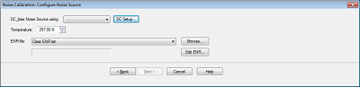
    • Use Noise Source - A noise source is used to characterize the low-noise receivers.

    • Use Power Meter - A Power Meter/Sensor is used to calibrate a VNA source, which then is used to characterize either the low-noise receivers or a VNA receiver.  This selection is made for you and can NOT be changed when NA Receiver is selected on the Noise Figure Setup dialog.

      Note: (M9485A) Select Internal for Power > Leveling & Offsets > ALC Hardware setting  

    • Meas Noise Params - Perform pulling measurements using a variety of impedances to characterize the noise parameters of the noise receiver.  These are measured by default.  If unselected, no pulling measurements will be performed and the GammaOpt of the noise receiver will be assumed to be idealized (see Noise Parameters definitions below for description of GammaOpt).  Turning noise pull measurements off is useful if there is a lot of loss between the output port cal plane and the receiver, or if the number of standards that can be used for pulling is small (for instance, when using mechanical standards and/or CalPods).  

    Source Temperature

    Use 302K for Vector Noise Cal with internal/ECal tuner  When checked will use 302K as the source temperature when vector correction is applied and the tuner is an ECal or internal tuner. When unchecked, the specified source temperature will be used.


    Configure Noise Source dialog box help

    DC Bias Noise Source using Select the required noise source from selection.

    DC Setup Setup the external DC source.

    Temperature  Specify the current temperature at the Noise Source connector.  The Noise source is kept ON during noise figure measurements. This results in the Noise Source being a few degrees warmer than Ambient temperature, and a more accurate calibration. See Noise Figure tips to learn more about the significance of temperature.

    ENR File  Select the Noise Source ENR file. If not already there, copy your Noise Source ENR file to the VNA C:/Program Files/Keysight/Network Analyzer/Noise folder. Then click Browse to find the ENR file.

    Clear ENR List  Scroll to the bottom of the ENR list, then click to remove the selected ENR file. Then browse or select to find a new file.

    Edit ENR   Click to launch the ENR Editor dialog box which is used to change or create ENR files. This is NOT usually necessary.


    See Noise Source requirements.


    Configure Noise Source dialog box help

    DC Bias Source using  Select 28 V Rear Panel for PNA or External Source for PXI

    Use USB Noise Source  Select the required noise source from selection.

    Temperature  Specify the current temperature at the Noise Source connector.  The Noise source is kept ON during noise figure measurements. This results in the Noise Source being a few degrees warmer than Ambient temperature, and a more accurate calibration. See Noise Figure tips to learn more about the significance of temperature.

    ENR File  Use USB Noise Source Internal File or select the Noise Source ENR file. If not already there, copy your Noise Source ENR file to the VNA C:/Program Files/Keysight/Network Analyzer/Noise folder. Then click Browse to find the ENR file.

    Clear ENR List  Scroll to the bottom of the ENR list, then click to remove the selected ENR file. Then browse or select to find a new file.

    Edit ENR   Click to launch the ENR Editor dialog box which is used to change or create ENR files. This is NOT usually necessary.


    See Noise Source requirements.


    Click either Create or Edit to launch the same dialog box, shown below.

    Edit / Create ENR File dialog box help

    ENR Numeric Data

    Use Previous and Next buttons to scroll to Entry # to edit. Type ENR value in  dB, then press Enter.

    Done  Click when finished editing all values. Then click Store ENR File to save the file.

    Identifying Data

    Model # of the Noise Source. This can NOT be changed.

    Serial # of the Noise Source.

    Temperature and Humidity in which the Noise Source was calibrated. This is for information only. The ENR data is always normalized to 290 Kelvin.

    KeyBd  launches a mouse-driven keyboard.

    Store ENR File  Click to launch a dialog to save the new or edited ENR file.


    Select DUT connectors and Cal Kits dialog box help

    Port 1  and Port 2

    DUT (Device Under Test) Connectors  Specify the connector and gender of the DUT.

    Cal Kits  Select the Cal Kit to be used to calibrate each test port. The list for each DUT Port displays kits having the same connector type as the DUT. Using incorrect calibration standards can significantly degrade measurement accuracy. Learn more.

    Power Sensor  Used to calibrate the source port. Specify the connector and gender of the Power Sensor.

    Noise Src  Used to calibrate the noise receivers. Specify the connector and gender of the Noise Source. The Keysight 346C has an "APC 3.5 male" connector.

    Note: For highest accuracy, the noise source should be connected as close as possible to the VNA port 2 connector. This causes the largest difference between the Noise Source HOT (on) and COLD (off) settings.

    For both Cal devices (power sensor and noise source, specify the connector type and gender. When the Cal device connector is NOT the same type and gender as the DUT Port connector, then for optimum accuracy, extra cal steps are used to measure and correct for the adapter that is used to connect the Cal device to the reference plane.

    Select Ignored (at the bottom of the DUT Connectors list) to NOT compensate for the adapter.

    Select the Cal Kit that will be used for that process.

    De-embed power sensor adapter / noise source adapter / thru adapter The VNA uses the connector type and gender of the DUT along with the connector type and gender of the cal device to determine if an adapter removal operation is taking place AND whether or not that removal operation requires an additional cal step.  

    However, the use of the connector type can, in special cases, hide the need for the extra cal step.  Check the "De-embed..." box in these cases to inform the VNA that the extra step is needed.

    Such a case is illustrated below where the noise source is connected close to test port 2 for higher accuracy. If unchecked, the VNA would assume in this case that the Noise Source is connected to the Thru standard at the port 1 (DUT input) reference plane. A similar situation occurs when the power sensor connector does not match the input DUT connector, but does mate with the output DUT connector. The VNA would assume in this case that the power sensor is connected to the Thru standard at the port 2 (DUT output) reference plane. In both cases, the prompt will clarify that the adapter is expected to remain in-place during the Thru connection.


    Source Cal Settings  Click to launch the Source Power Cal (for apps) dialog. This dialog is used to set Power Meter / Sensor settings for both the Port 1 Power Cal, and the optional LO Power Cal.

    Modify Cal  Check, then click Next, to Modify Cal (Standards AND Thru Method).

    Display Smith Chart During Cal  Smith Chart is selected as format during calibration measurement.

    Note: Enhanced Response Calibration is NOT supported with noise figure.


    Measure Standards Steps dialog box help

    Power Level at which to perform the Power Cal.

    It is usually best to set power level to 0 dBm at the power sensor because the power sensor is calibrated at that level. Lower power levels will yield a slower and noisier calibration.

    However, with the default source attenuation (10 dB or 20 dB depending on the model), the VNA may not be capable of achieving this power level at higher frequencies. To check the max leveled power, view an R1 (port 1 reference receiver) trace over the frequency range of interest, then increase the power until roll-off appears. Power levels at the test port may be approximately 2 dB lower than at the R1 receiver.

    If an external component is used between the VNA test port and the calibration reference plane, then adjust the power level so that the power at the sensor is about 0 dBm if possible.

    The current source attenuation value is shown on the dialog.

    Connect Noise Source to the Port 2 measurement (reference) plane

    When the "De-embed Adapter.." boxes are checked, additional cal steps are required.

    Subsequent Steps

    Connect Port 1 to Port 2 - Connect port 1 reference plane to the port 2 reference plane using the required Thru standard or adapter.

    Connect ECal to Ports 1 and 2 - Connect the ECal module between the port 1 reference plane and the port 2 reference plane.

    Validate Noise Source Cal

    To validate a Noise Source calibration, connect the Noise Source to Port 2 and measure ENR.

    Compare the measured values to the values in the ENR table.

    How to manually turn the Noise Source ON | OFF

    1. Press Power > Main > Noise Source.