This topic contains the following information:
S-Parameters (pre-selected ratios)
Ratioed (choose your own ratio)
Unratioed Power (absolute power)
Option Sx090A/B Spectrum Analyzer Measurement Parameters (separate topic)
Option S93070xB Modulation Distortion Measurement Parameters (separate topic)
Option S93031xB Phase Noise Measurement Parameters (separate topic)
Learn about Balanced Measurements
See other 'Setup Measurements' topics
S-parameters (scattering parameters) are used to describe the way a device modifies a signal. For a 2-port device, there are four S-Parameters. The syntax for each parameter is described by the following:
S out - in
|
out = |
analyzer port number where the device signal output is measured (receiver) |
|
in = |
analyzer port number where the signal is applied (incident) to the device (source) |
Move the mouse over each S-parameter to see the signal flow:
For two-port devices:
When the source goes into port 1, the measurement is said to be in the forward direction.
When the source goes into port 2, the measurement is said to be in the reverse direction.
The analyzer automatically switches the source and receiver to make a forward or reverse measurement. Therefore, the analyzer can measure all four S-parameters for a two-port device with a single connection.
See the block diagram (including receivers) of your VNA.
|
Reflection Measurements |
Transmission Measurements |
|
|
All analyzer models have test port receivers and reference receivers.
For 4-port models...
R1, R2, R3, and R4 are reference receivers. They measure the signal as it leaves the analyzer source.
R1 measures the signal out of Port 1
...
R4 measures the signal out of Port 4
A, B, C, and D are test port receivers. They measure the signal out (or reflecting off ) of the DUT.
A measures the signal into VNA Port 1
B measures the signal into VNA Port 2
C measures the signal into VNA Port 3
D measures the signal into VNA Port 4
Models with more than 4 ports must specify receivers using Logical Receiver Notation. Learn more.
Ratioed measurements allow you to choose your own ratio of any two receivers that are available in your analyzer. S-parameters are actually predefined ratio measurements. For example S11 is A/R1.
The following are common uses of ratioed measurements:
Comparing the phase between two paths of a device. An example could be something simple like a power splitter or more complicated like a dual-channel receiver.
Measurements that require a higher dynamic range than the analyzer provides with S-parameters.
The unratioed power parameter measures the absolute power going into any of the receivers that are available on your analyzer.
The reference receivers are internally configured to measure the source power for a specific analyzer port.
Measuring phase using a single receiver yields meaningless data. Phase measurements must be a comparison of two signals.
Averaging for Unratioed parameters is computed differently from ratioed parameters. Learn more.
To calibrate ratioed or unratioed receiver (power) parameters, the recommended method is the Guided Power Calibration. The Unguided Response Calibration can also be used to calibrate a single unratioed or ratioed parameter at a time.
Click a tab to create or change measurements.
TabsS-Parameter Select a predefined ratioed measurements. Learn more about S-parameters. For Setup:<= 4-Port
For Setup: Multiport (>4 ports) Note: Greater than 4 ports is not supported on the P937xA.
Balanced Select a balanced measurement type. Topology Click to invoke the Balanced DUT Topology / Logical Port mappings dialog box. Learn more about Balanced Measurements. For Setup:<= 4-Port
For Setup: Multiport (>4 ports) Note: Greater than 4 ports is not supported on the P937xA.
The table only show parameters for up to the first four VNA ports being used. Balanced Parameter Selector at the bottom allow you to select other parameters.
Multiport setup is shown in Custom under Topology. The setting in Custom only can change with SCPI command. Select All Will only select the parameters shown and will not select the check box of the Receiver selector at the bottom.
Receivers Select receivers to make Ratioed and Unratioed (absolute power) measurements. Learn more about receiver measurements.
Ratioed Click on the check box to select the parameters and create measurement. Receiver selector at the bottom allow you to define ratios. Select a receiver for the Numerator, select another receiver for the Denominator, then select a source port for the measurement. The Source port is ALWAYS interpreted as a logical port number. For convenience, the table is populated with common choices. Select All Will only select the parameters shown and will not select the check box of the Receiver selector at the bottom. Unratioed Same as Ratioed, but select 1 as the Denominator. Waves Select receiver notation to make ratioed and unratioed measurements.
Click on the check box to select the parameters and create measurement. Wave selector at the bottom allow you to define ratio. Select All Will only select the parameters shown and will not select the check box of the Wave selector at the bottom.
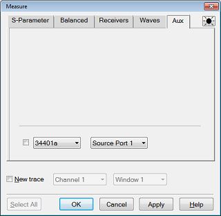
AUX Select input of Auxiliary on the rear panel to make DC measurement.
Note: Aux Tab is shown when the M9341B is installed or Active - Show in UI for the external device is checked.
Click on the check box to select the input of auxiliary and create measurement. Auxiliary selector at the bottom allow you to define auxiliary and other parameters such as PMAR and DVMs. AuxIn range Click on the drop down selection to select the DC range. Select All Will only select the parameters shown and will not select the check box of the Auxiliary selector at the bottom. AUX Select input of Auxiliary on the rear panel to make DC measurement.
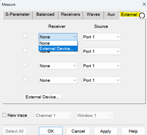
External Select external receiver traces (e.g. Power Meters, DC Meters, SMUs).
Receiver Allows users to select the external receiver. Will show all external receivers (Power Meter, DC Meter and SMU) defined in the External Device Configuration dialog which have "Active - Show in UI" enabled. Source Select the active source for the measurement. New trace Click to allow multiple external receiver traces to be selected. If "New Trace" is enabled, then multiple checkboxes maybe selected. External Device... Click on this button will open the External Device Configuration dialog. Channel / Window Selections
These selections are NOT AVAILABLE when changing an EXISTING measurement. Learn how to change a measurement. Channel Number Select the channel for the new traces. Create in New Window
About Measurement Parameters (top of page) |
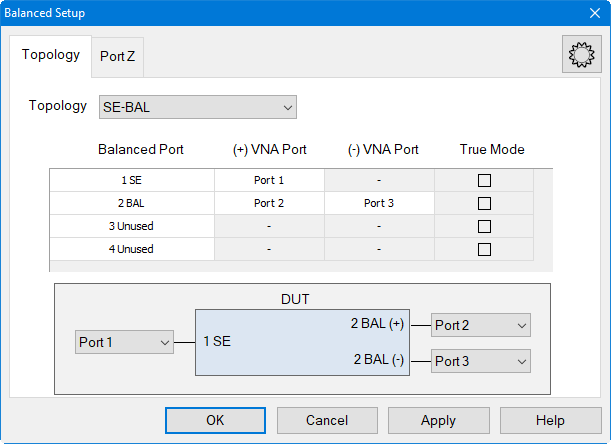
Topology Tab
Create or edit DUT Topology and Logical Port Mapping. A Logical Port is a term used to describe a physical analyzer test port that has been remapped to a new port number. You can assign logical single-ended ports to logical balanced ports. Note: These selections apply to ALL measurements in the channel. If the device topology is changed, any existing measurements in the channel that are incompatible with the new topology will be automatically changed to one that is compatible. Topology: Describes your DUT as you would like it tested. The following device topologies can be measured by a multiport analyzer.
These topologies can be used in the reverse (<==) direction to measure:
For example, to measure a Balanced / Single-ended topology, measure the S12 (reverse direction) of a Single-ended / Balanced topology. A balanced port can be any one of four physical port combinations: 1 - 3 1 - 4 2 - 3 2 - 4
Balanced Port Number of rows equals number of VNA ports. User may select each port as SE or BAL or Unused. Unused ports are always forced to the bottom of the list and some Unused port selectors may be grayed-out when all the VNA ports are used. VNA Port Displays physical port numbers. But will display logical port numbers if logical ports are used. Balanced port requires (+) and (-) VNA port definitions; SE port only requires a single VNA port definition. True Mode Define true mode independently for each BAL port. SE ports cannot be defined as true mode. This function is not supported in model M980xA and P50xxA. So the checkbox is grayed out.
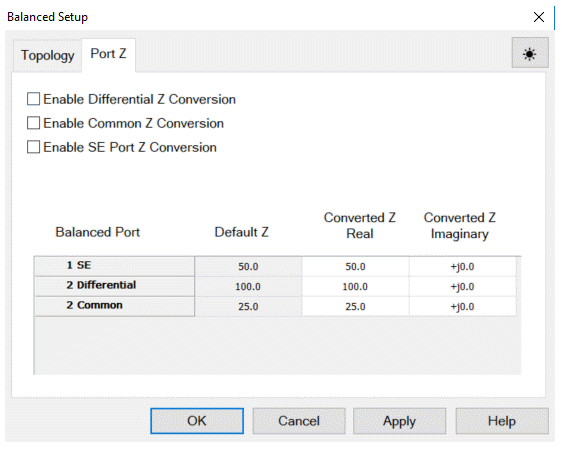
Port Z Tab
Provide an enable for both Common and Differential Conversion and SE Port Z Conversion. Balanced Port Shows all ports defined on the balanced topology page. Default Z Shows the default impedances that will be applied if the port Z conversions are not enabled. The SE Default Z always equals the System Zo defined for the VNA. The Differential and Common Default Z will display values calculated from the single-ended port impedances. Converted Z User may enter the real or imaginary component of the impedance. Power Waves (default) This was legacy method used. If a load is the complex conjugate of the system impedance, then it will be displayed as a perfect match. Traveling Waves This is newly added. If a load equals the complex system impedance, then it will be displayed as a perfect match.
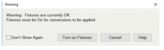
Warning Dialog The dialog is displayed if "Conversion" is enabled and "Apply Fixtures" is currently disabled. See Also
|
|