Attenuator Setup
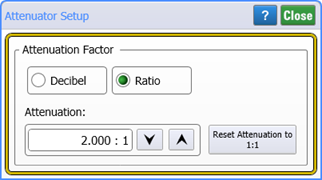
Use the Attenuator Setup dialog to specify attenuation introduced by an external device in your test setup. This allows FlexDCA to report measurement values as if the measurements were made before the attenuator rather than at the oscilloscope's channel input. You can select to enter attenuation in decibels, voltage ratio (electrical channels), or power ratio (optical channel). The default units are decibels. Clicking Reset Attenuation to 1:1 resets the attenuation to the default value of 0 dB (1:1).
When entering attenuation in decibels, enter the attenuation as a positive value into the Attenuation field. Gain is implied when you enter negative decibel values.
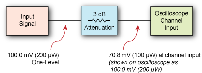
For example, if your test setup included an electrical signal with 3 dB of attenuation, a signal with a 100.0 mV one level (before the attenuation) would be measured as 70.8 mV at the oscilloscope's channel input. However, after entering 3 dB (or 1.413:1 ratio) of attenuation compensation, the corrected oscilloscope measurement would read 100 mV.
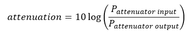
Optical Signals
Attenuation is expressed differently depending on the type of signal applied. For an optical signal the following equation applies. With a 6 dB attenuation setting, the signal is interpreted as being four times the channel input level.
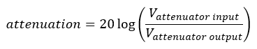
Electrical Signals
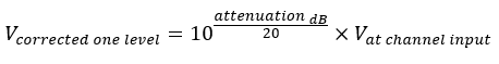
The following equation shows attenuation for an electrical signal. For a 6 dB attenuation setting, the signal is interpreted as being double the channel input level.
With an attenuation factor expressed in decibels, the conversion of the channel input value would be:
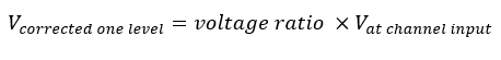
With an attenuation factor expressed as a voltage ratio, the conversion of the electrical channel input value would be:
Effects on Channel Settings
When compensating for an external attenuator, the channel settings change in the following ways:
- The unit values and amplitude of the markers and vertical measurements reflect the signal at the input of a transducer, probe, attenuator, or amplifier.
- The maximum and minimum vertical scale settings change by a specified factor.
- Offset minimum and maximum values change by a specified factor.
Gain is implied when you enter negative decibel values or ratios of less than 1:1 in the Attenuation field.
The default attenuation value is 1:1 when no active probes are connected to the instrument. When an active probe such as the N2800A is connected, the default value is the nominal value of the probe and the Reset Attenuation to 1:1 button is unavailable.
For electrical channels, the value displayed in the Attenuation field is the same value displayed in the N1000A's Probe tab of the All Calibrations dialog; changing one value will change the value of the other.
For both power and electrical signals, the available attenuation ratio range is 0.0001:1 to 1,000,000:1. This is equivalent to –40 dB to 60 dB for power, and –80 dB to 120 dB for electrical signals.