Channels and Slots
Channels and Slots
The N1000A has four slots in which you can install the plug-in modules. Single-slot modules can be installed in any available slot. Two-slot modules can occupy slots 1 and 2 or 3 and 4. They can not span slots 2 and 3.
As shown in the following picture, the Channel Bar, located along the display's bottom edge, contains buttons and information about each input channel.
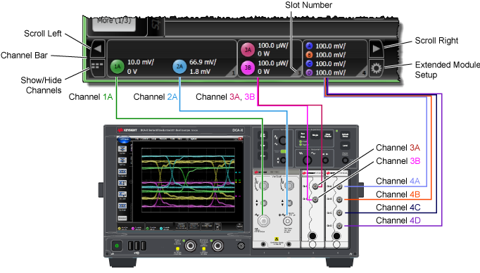
Channels are identified by the slot number followed by the channel letter. On N1040A-series modules, the channel letters by increase in alphbetical order starting from the top connector. On all other modules, the channel letters increase from left to right. Click a channel button to turn electrical channels and optical channels on or off and to enter precise values for channel scale and offset. When several channels are turned on, some may be hidden in the Channel Bar. Click the Scroll Left and Scroll Right buttons to bring the hidden channels into view. Or, click the Show/Hide Channels button to show all Channel buttons in the Channel bar. Click the Extended Module Setup button to view the Extended Module Setup dialog from which you can assign external instruments and simulated channels to the N1000A.
A total of sixteen module input channels are possible, if you install four single-slot N1045A-04M or -04F modules. FlexDCA can simultaneously display and perform measurements on all 16 measurement channels. Additional four simulated slots (5 through 8) are available for:
- External modules (connected via LAN or USB). Examples of external modules include DCA-M modules or an optical switch.
- Simulated modules
Turning the channel off also turns off the markers assigned to that channel.
When an autoscale is performed, FlexDCA automatically attempts to identiy the signal type on each input.
| Connector | Description |
|---|---|

|
Electrical input connectors are located on plug-in modules.
|

|
Optical input connectors are only available on plug-in modules with internal optical channels.
|

|
Beneath the channel connectors on most modules is located a probe-power connector, which provides power to recommended active probes. |
Protecting Electrical Channels
Electrical channels can be used to perform measurements on tributary electrical signals, evaluate receiver performance in transceiver testing, use available external optical receivers, and perform general purpose measurements.
- ESD protection
- Electric Overload Stress (EOS).
 The Keysight N9355CK01 is a DC coupled limiter (DC to 26.5 GHz) that is used to protect sensitive oscilloscope channels from damage due to electric overload stress (EOS) and electrostatic discharge (ESD). For example, voltages in excess of ±2V can damage high-performance samplers used in oscilloscopes. The limiter dramatically reduces the likelihood that such voltages will reach the sensitive part of the instrument, ensuring that the oscilloscope will perform reliably. Step generators within the N1055A TDR module uses
≤0.2V, which is less than the diode threshold of the N9355CK01 limiter. The N9355CK01's voltage drop is ±0.6V to 0.7V at ±10 mADC.
The Keysight N9355CK01 is a DC coupled limiter (DC to 26.5 GHz) that is used to protect sensitive oscilloscope channels from damage due to electric overload stress (EOS) and electrostatic discharge (ESD). For example, voltages in excess of ±2V can damage high-performance samplers used in oscilloscopes. The limiter dramatically reduces the likelihood that such voltages will reach the sensitive part of the instrument, ensuring that the oscilloscope will perform reliably. Step generators within the N1055A TDR module uses
≤0.2V, which is less than the diode threshold of the N9355CK01 limiter. The N9355CK01's voltage drop is ±0.6V to 0.7V at ±10 mADC.
The N9355CK01 will protect instruments from occasional and short voltage spikes. A major power source, such as a high voltage and current supply can still cause severe damage to the limiter itself, or the instruments. Operators should continue using industry standard EOS and ESD practices to minimize this risk.