External Scaling
Instrument:
N1000A
Flex Apps:
FlexDCA
Meas. mode:
TDR/TDT
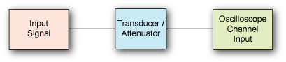
External scaling enables you to set the displayed voltage (or power) scale to levels defined by the insertion of an external device between the instrument and a signal source. You can enter the gain or attenuation of an external device or change the measurement units or offset of a transducer to effect changes to scaling.
External scaling can be entered for electrical and optical channels. You make the changes from the External Hardware Setup dialog, which links to the following dialogs:
Examples of Using External Scaling
- When an attenuator is used to reduce an optical source's power level below a channel's maximum input level. If you add a 10 dB attenuator, the power is reduced by a factor of 10:1. Although the power levels into the channel are within acceptable limits, your source measurements will be 1/10th of the actual source level. External scaling allows you to compensate for the 10 dB attenuation so your measurements reflect the source level prior to attenuation.
- When compensating a device's gain or loss to a channel input. This occurs for clock recovery plug-in modules, probes, attenuators, or amplifierst. For example, you can connect a probe to a channel and enter the probe attenuation ratio. The channel information is then scaled to the signal levels at the probe tip. You can adjust the externally scaled ranges in the Scale and Offset boxes found in the Channel dialog.
- When using a transducer, such as an O/E or E/O device, at a channel input. You can convert the displayed measurement units to indicate the levels at the transducer input. An example of O/E transducer conversion would be a photodiode output connected to an electrical channel. Although the photodiode output is electrical (volts), you can change the scaling to indicate the units applied to the photodiode input (watts).
- Clock recovery modules are considered to be external devices when referenced to a channel input. Signals are attenuated when they pass through one of these modules.