DiCon GP750 Switch Ports
Example DiCon GP750 Switch's Switch IDs
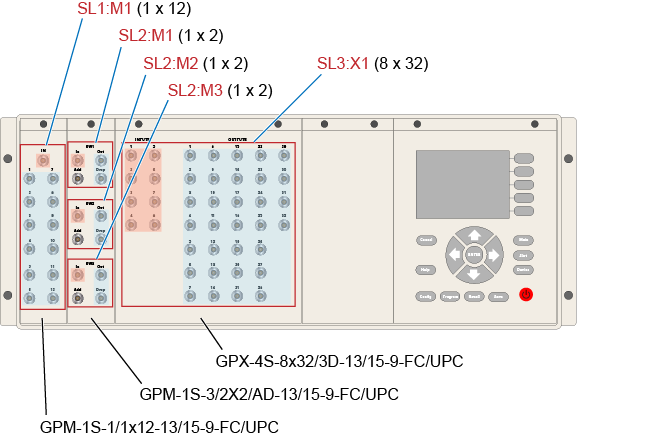
The following picture shows how the GP750 switch modules are named. The ID strings for matrix switch modules include an "X" character and for 1 x N switches includes an "M" character. The ID string takes the form: <slot-ID>:<module-ID>. On the DiCon-GP750 shown here:
- Slot 1 switch is a 1 x 12 switch with an ID of SL1:M1.
- Slot 2 switches are 1 x 2 switches that have the following IDs: SL2:M1, SL2:M2, and SL2:M3. These switches include an Add port which is passive and not used with FlexOTO. The In, Out, and Drop ports are active.
- Slot 3 switch is 8 x 32 switch matrix with ID SL3:X1.
FlexOTO expects that the test equipment be connected to the switch ports as marked in the following table. You can disregard the switch's front panel INPUTS and OUTPUTS labels as these switches are bidirectional, and FlexOTO needs the larger number of ports to be assigned to Fixtures, Demultiplexers, and Impairments.
Because DiCon offers many configurations of installed switch modules, your switch may not match this picture.
Because switches SL1:M1, SL2:M1, SL2:M2, and SL2:M3 only have one switch output, an output is unavailable to a demultiplexer, impairment, or user instrument.
| Front Panel | ||||||
|---|---|---|---|---|---|---|
|
||||||
| Switch SL1:M1 | Switches SL2:M1, SL2:M2, and SL2:M3 | Switch SL3:X1 | ||||
| Front Panel Label | Ports 1 through 12 | IN | Out and Drop | In | OUTPUTS (Ports 1 through 32) |
INPUTS (Ports 1 through 8) |
| Port Function in FlexOTO | Inputs From | Outputs To | Inputs From | Outputs To | Inputs From | Outputs To |
| DCA-M Modules | ● | ● | ● | |||
| Fixtures | ● | ● | ● | |||
| Demultiplexers | ● | ● | ||||
| Impairments | ● | ● | ||||
| User Instruments | ● | |||||
| Color definitions in table: | ||||||
| Switch ports that FlexOTO considers to be switch inputs. | ||||||
| Switch ports that FlexOTO considers to be switch ouputs. | ||||||
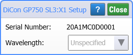
| Hardware Diagram Switch Block | Switch Setup Dialog (To open, click on Switch Block) |
|---|---|
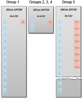
|
|